Chapter II. Hammer Map Editor.

Complete guide to Valve Hammer Editor: installation, interface, tools, menus, scale, shortcuts, and extracting resources from pak0.pak.

2.1

Latest Version of Hammer

2026 update. Hammer 3.5 was the last Hammer branch made for GoldSrc, so this section is historical. It is still useful if you want to follow the original screenshots. For daily work, consider J.A.C.K. if you want a Hammer-like editor, or TrenchBroom if you prefer a modern cross-platform brush editor that works with MAP/Valve 220 files.
In April 2003 A new version of the map editor Valve Hammer Editor 3.5 (public beta) has been released.

Download

If you create maps for CS, then you need to download CS Expert FGD. Here is a link to Half-Life FGD. This is an updated version of the FGD file with support for the new map editor feature of showing models in 3D view. If you wish, you can independently attach the model display to the CS FGD file you are using by cutting out the required piece of code from the file for Half-Life. How to do this is described below.

Major changes

  • models are now displayed directly in the editor's 3D view
  • You can now load a PTS file (to search for the LEAK error) directly into the 3D view of the editor
  • modified FGD files for HL and DoD
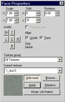
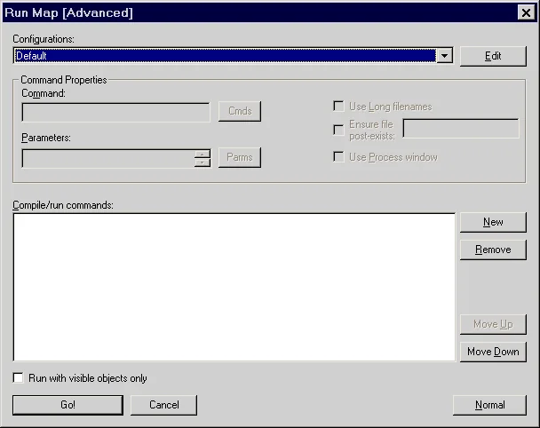
  • The panel for working with textures and the Expert compilation window have been redesigned
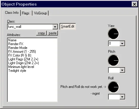
  • Pitch, Yaw, Roll parameters are now divided into several compasses in the properties of entity objects
  • added "animate models" checkbox to editor options
  • ability to specify the display distance of models in 3D view
  • ability to select animations for models
  • ability to change background color in 3D view
  • models containing masked textures now appear transparent
  • more features in the final version

More information about the changes

1. Display models in 3D view
Now models are shown directly in the 3D view of the editor, but for this function to work, you need to download and connect a new FGD file to the editor (links are given above).
You can edit your FGD file yourself if you don't want to download a new one. In this case, you need to do 3 conditions:
  1. In the editor settings, in the "Tools\Options\Game Configurations" menu, you must fill in the "Game Directory" and "Mod Directory" fields;
  2. If you will use models from a PAK file (valve\pak0.pak), then they must be unpacked into the appropriate directory;
  3. You need to add some information to the FGD file, this can be done two ways:
    1. @PointClass studio() = entity_name
      [
           model(studio) : "Model"
      ]
      In this case, the entity object (whose name is specified instead of the words entity_name) is displayed as a single-color rectangular object until the path to the model is specified (we are used to this display), but as soon as we specify the path to the model, instead of the rectangular object we will see the model itself.
    2. @PointClass studio("models/some_model.mdl") = entity_name []
      In this case, the entity object (whose name is specified instead of the words entity_name) is always displayed as the same model, the path to which is specified here: studio("models/some_model.mdl").
We recommend adding information for the "cycler" (and "cycler_sprite") object according to the first sample, and for the "info_plaer_start" and "info_plaer_deathmatch" objects - according to the second.
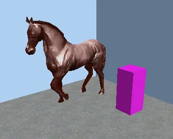
The picture below shows that if the path to the model is specified in the properties of the "cycler" object (namely, it inserts the model onto the map), then the model is displayed; if the path is not specified, a single-color rectangular object is displayed.
New Hammer Editor Feature - Show Models in 3D View
The maximum distance in a 3D view at which models are still displayed can be set in the editor properties ("Tools\Options\3D views"). Possible values ​​are from 0 to 2000 units. When this maximum distance is exceeded, the models turn into single-color rectangular objects.
So far, in the beta version of the editor there is a small bug when textured models turn into white (without textures). This has something to do with how OpenGL works and will hopefully be fixed in the final version.
Also on this tab you can enable/disable the display of animations for models (the "Animate models" checkbox). There is also a "Pick Background Color" button, with which you can select a background color in the 3D view of the editor.
t2new hammer3 2. Separated parameters Pitch, Yaw, Roll
Now the Pitch, Yaw, Roll parameters in the properties of entity objects each have their own compass. True, Pitch and Roll don't work yet.
t2new hammer1 3. Changed texture panel
Now the textures panel looks like this:
t2new hammer4 4. Changed compilation window
The compilation window in "Expert" mode has been slightly modified:
t2new hammer2
2.2

Installing and Configuring Hammer

Modern setup. The paths and dialogs below still explain how Hammer is wired together, but replace the old packages with current ones. If you use Hammer, set the Build Programs paths to sdHLCSG.exe, sdHLBSP.exe, sdHLVIS.exe, and sdHLRAD.exe from SDHLT, or to the matching VHLT executables. If you use J.A.C.K., save regular work in JMF and export MAP when needed. If you use TrenchBroom, keep the project in Valve 220 MAP format and compile with external GoldSrc tools. Add the compiler package's WAD and FGD files, for example sdhlt.wad and sdhlt.fgd, when the toolchain requires them.
In this article we will describe in detail how to install and prepare the Hammer editor for use. To successfully use the editor we will need:
  1. Valve Hammer Editor
  2. ZHLT 2.5.3 or ZHLT 2.5.3 (Custom Build)
  3. Halflife-CS-Expert.fgd
First we will install the map editor. Then we will connect to it an FGD file with a description of the entity objects. And finally, we will indicate in the editor the paths to the compiler programs (ZHLT).
So, let's launch the installation exe file and select the installation directory (ATTENTION! Place the editor and compilers on 1 logical drive with Half-Life), we selected D:\Hammer. A few more clicks on the "Next" button and Hammer is installed. Now you need to specify the paths where the editor will search for the FGD file and ZHLT compilers.
Several preparatory operations
  1. Let's create an additional folder ZHLT ("D:\Hammer\ZHLT"). Let's copy the contents of the archive with compilers into it (zhlt253.zip or, if you decide to use the improved ZHLT Custom Build compilers, then the contents of the archive with improved compilers);
  2. Let's copy the file halflife-cs-expert.fgd from the halflife-cs-expert.zip archive to the folder "D:\Hammer\fgd\counter-strike". This directory already contains a standard fgd file for cs, but we will use its improved version;
  3. Copy the sprites from the halflife-cs-expert.zip archive (folder "sprites/cs") to the folder "D:\Hammer\sprites\cs".
This completes the preparatory part. Let's move on to setting up Hammer.

Editor setup

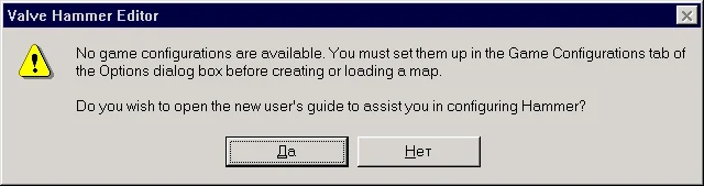
When you launch Hammer for the first time, a window will appear asking you to display help on setting up the editor. The purpose of this article is precisely to help you configure the editor, so you can click "No".
t2wcmes Then a window with editor settings will appear. Let's look at each tab separately. Note: some options will remain unclear to you now. Later, once you've gotten comfortable with the editor, you can experiment with different settings.
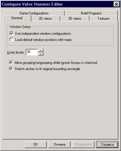
1. General tab (Hover over the option of interest for a description.)
On the "General" tab, you should pay attention to the "Use independent window configurations" checkbox, which determines how many editing windows you will see. The checkbox is checked - one window, not checked - four.
t2wcopt1
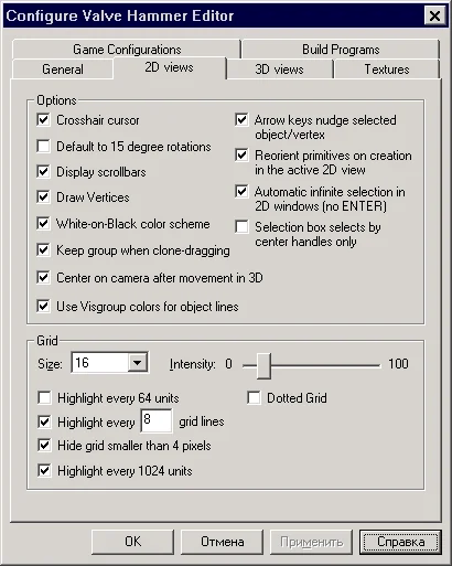
2. 2D views tab (Hover over the option of interest for a description.)
We recommend setting everything as in the picture (we think these are pretty optimal settings). Later, having figured out what each of the options means, you can set the settings that are convenient for you.
t2wcopt2
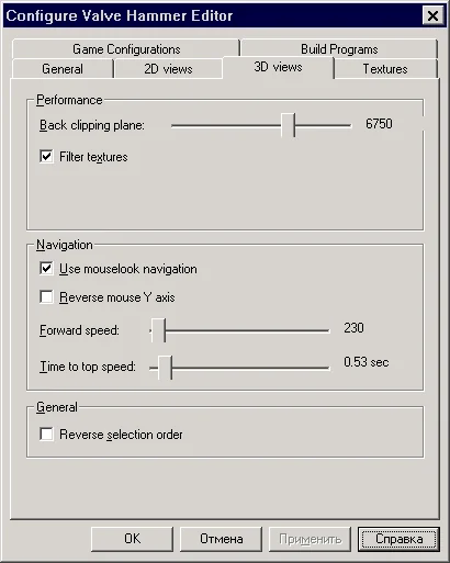
3. 3D views tab (Hover over the option of interest for a description.)
t2wcopt3
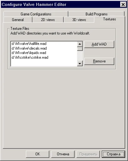
4. Textures Tab
Texture control window. Here you can connect or, conversely, remove WAD files with textures. You can use textures from the listed WAD files on your map.
To get started, we recommend adding 4 standard WAD files:
  • valve/halflife.wad
  • valve/decals.wad
  • valve/liquids.wad
  • cstrike/cstrike.wad
t2wcopt4 Connect the following WAD files from the valve folder no need (since they do not contain suitable textures for use):
  • (don't connect) cached.wad
  • (don't include) fonts.wad
  • (do not connect) gfx.wad
  • (do not connect) spraypaint.wad
If you want, you can connect a few more WAD files from the cstrike folder.
High-quality WAD files from the cstrike folder:
  • chateau.wad
  • cs_bdog.wad
  • cs_havana.wad
  • de_piranesi.wad
  • torntextures.wad
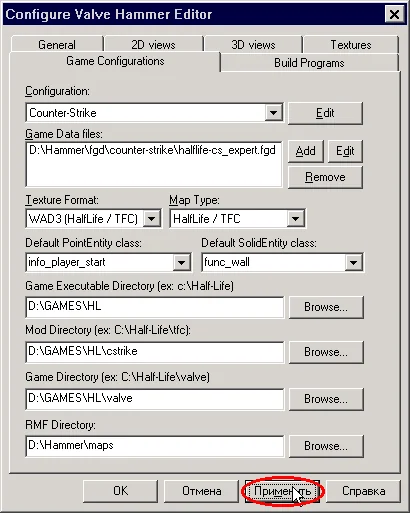
5. Game Configurations Tab (one of the main editor settings windows)
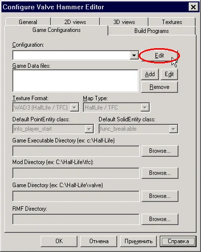
First you need to create a new configuration. Click the "Edit" button (see figure below).
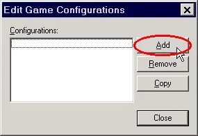
t2wcopt5 In the window that appears, click the "Add" button.
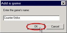
t2wcopt51 Next, enter the name of the configuration (any). We called it "Counter-Strike". Click "OK".
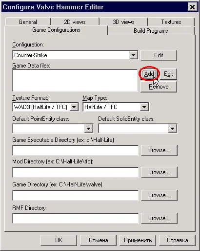
t2wcopt52 Now the previously shaded fields are available. Let's include an FGD file with records about entity objects. Click the "Add" button (see figure below).
t2wcopt53 Do you remember we copied the file halflife-cs-expert.fgd to the folder "D:\Hammer\fgd\counter-strike", so we indicate this path. Now the editor knows that we will build maps for CS :)
Now let's fill in the remaining parameters and lines. Place everything exactly the same as in the picture (of course, you will have your own paths).
t2wcopt54 Texture Format And Map Type
Let's leave it as is. Moreover, you can't choose another :) Everything is correct here.
Default PointEntity class
This specifies the type of point entity object created by default. This option is just for convenience. Usually the info_player_start point object is created first on the map, so we recommend selecting it.
Default SolidEntity class:
This specifies the type of brush entity object created by default. Func_wall is used quite often on maps and in large numbers, so it makes sense to select it from the list. This option is needed simply for convenience in the subsequent creation of the map.
Well, finally, we indicate the paths:
  • Game Executable Directory: to the folder with Half-Life
  • Mod Directory: to cstrike folder
  • Game Directory: to the valve folder
  • RMF Directory: to the folder where the sources of our maps will be stored (specify "D:\Hammer\maps")
Well, save all the settings with the "Apply" button.
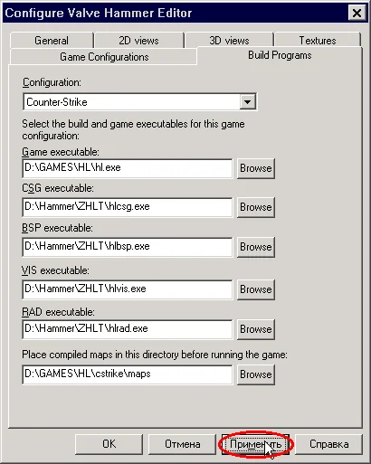
6. Build Programs Tab
The "Build Programs" tab must be filled out if you will compile your maps in the Hammer editor. Most likely, this will be the case at first :), so fill it out. Why "at first"? It's just that later we will convince you that maps need to be compiled not in Hammer, but as a BAT file.
t2wcopt6 First we specify the path to hl.exe.
Then the paths to the compilers (remember, they are located in "D:\Hammer\ZHLT").
  • CSG executable: path to the file hlcsg.exe
  • BSP executable : path to the file hlbsp.exe
  • VIS executable: path to the hlvis.exe file
  • RAD executable: path to the file hlrad.exe
The last line is the path to the folder where the finished map will be placed after compilation. We recommend specifying "cstrike\maps".
At this point, setting up the Hammer editor can be considered complete. Our editor is ready to go. It was simple, wasn't it? :)
2.3

Hammer Interface

In this article we will get acquainted with the Hammer editor interface, briefly describe its panels and main tools.
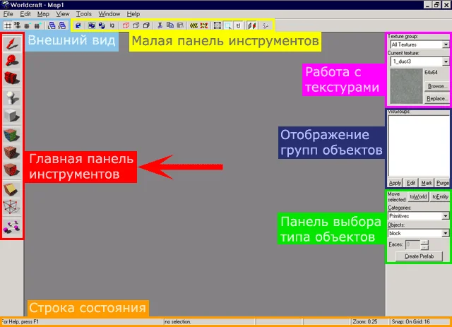
The Hammer editor has a total of 6 different panels plus a status bar. In the picture below you can see a general view of the Hammer editor and the names of the panels.
Hammer Editor Interface and Panels

1. Main toolbar

The main panel is the main one. Using the tools located on it, the map is created and colored. All other panels are auxiliary. The picture below briefly describes the functions of the tools and their names.
If you want to get acquainted with the functions of the main tools in more detail, read the following article Overview of Hammer Main Tools. t2wcinstruments

2. Appearance panel

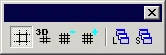
t2wcinstr sm1 Now let's look at the second panel (marked in blue in the very first picture), which controls some appearance parameters.
t2button01 — show/hide the grid; show/hide mesh in 3D view.
t2button02 — grid scale (decrease/increase).
t2button03 — load/save window layout (when using 1 editing window).

3. Small toolbar

t2wcinstr sm2 The small toolbar contains buttons that perform additional operations on objects, as well as some other functions. We recommend that you set everything exactly as in the figure above.
t2button04 - Carve function for cutting holes in objects. This function is described in detail in the article Creating Holes with Carve.
t2button05 — group/ungroup objects.
t2button06 — the Ignore Groups function is intended for editing individual objects from a group. When this button is turned on, the group of objects is temporarily ungrouped, and you can change individual objects.
t2button07 — hide selected objects; hide everything except selected objects; show all objects.
t2button08 — cut/copy/paste objects.
t2button09 — turns on/off the "cordon" mode; editing selection boundaries. "Cordon" mode is used to "cut out" any part of the map and subsequent compilation. For example, you are creating a large map. In this case, compilation can take quite a long time. We create a "cordon" selection, place the player's birth point inside the selected part of the map and compile only this part.
t2button10 — turns on/off the selection of objects only when you click in the center (on the central cross).
t2button11 — turns on/off automatic selection of multiple objects. If disabled, to select several objects you must additionally press Enter.

t2button12 — fixes textures on objects; when an object is rotated or displaced, the textures on it do not move (be sure to enable this option!).
t2button13 — a method for aligning textures (along the side of an object or relative to coordinates). Doesn't really matter, because... The alignment type can be changed at any time in the texture panel.
t2button14 — shows a window with map compilation parameters. This is where the compilation starts.

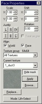
4. Panel for working with textures

t2wctexture The texture panel appears when you select a tool Texture Application . This panel contains buttons for aligning textures, changing their scale, and changing the overlay type. Here you can select individual WAD files in which you can view textures. There is also a function to replace one texture with another.
You can get more detailed information about map texturing in the fourth section of the Tutorial - "Textures and Decals".

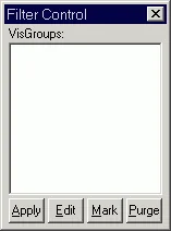
5. Panel for working with visual groups

t2wcvisgroup In this panel you can hide or show visual groups, i.e. combining several objects. Visual groups appear on this panel automatically when you use the "hide selected objects" buttons; hide everything except selected objects; show all objects."
Visual groups are highlighted by clicking the mouse (a palm appears). You can change the names and colors of visual groups with the "Edit" button. The "Mark" button highlights selected visual groups in 2D and 3D views. The "Purge" button removes visual groups that do not contain objects from the panel. The "Apply" button hides unselected visual groups in 2D and 3D views (i.e. those without a palm next to them :)

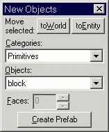
6. Panel for selecting the type of object to be created

t2wcobjects This panel is designed to select the type of object to be created. If you create simple brushes with the tool block , then such objects as cylinder, pyramid, corner will additionally become available on this panel. Prefabs are also managed through this panel.
If you create a point entity using the tool entity, then all possible types of point entity objects will be available in this panel.
The "To World" button turns a brush entity object into a regular brush;
The "To Entity" button turns the selected brush(es) into a brush entity object.
You can get more detailed information about creating brushes, entities and prefabs from the article How to Create a Brush, Entity, or Prefab?.

7. Status bar

The status bar displays: the type of selected object, cursor coordinates, size of the created or selected object, zoom, grid step in units.
t4helpline This concludes the article describing the Hammer editor interface.
2.4

Overview of Hammer Main Tools

In this article we will get acquainted with the main tools of the Hammer editor, with the help of which maps are actually created.
In the picture below you can see where the main toolbar is located (by the way, the position of any editor panels can be easily changed).
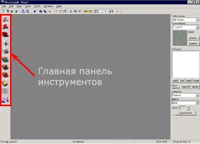
Hammer editor main toolbar
The picture below briefly describes the functions of the tools and their names. We will look at them in more detail below. t2wcinstruments
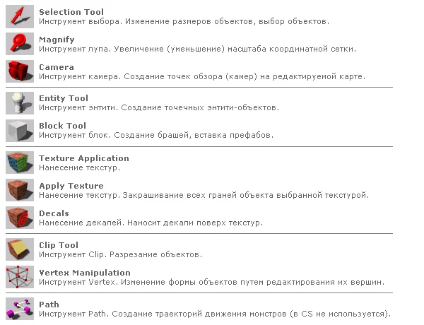
More about the tools

Now it is advisable that you launch the editor and try out the actions of the tools with us.
1. Selection tool (Select Tool)
t2wcinstr1 The arrow or selection tool serves several purposes. If you point this tool at any object in the editor, it will be selected (see the figure below). So far you don't know how to create objects, and your workspace is empty - return to this point after reading about the block tool (it is designed for creating objects).
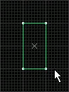
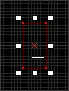
t2pic1 t2pic2 If you continue to click inside the selected object, you will be able to perform some simple operations with it such as resizing, rotating and parallel shifting. Let's talk about these operations in more detail.
  • a) Selector function: resizing
    To change the size of an object, you need to grab it by the white squares and drag it :)
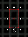
    t2pic7 t2pic8 b) Selector function: rotation
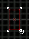
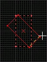
    Click inside the selected object 1 time to rotate it. Grab the white circles and pull.
    Note: in the editor settings, on the "2D views" tab, there is a "Default to 15 degree rotation" checkbox. So, if it is standing, then the rotation will be carried out at 15°. To smoothly rotate an object, you need to hold down Shift. If the checkbox is not checked, then everything is the other way around (check it yourself).
    We recommend rotating objects by 15 degrees only. The Half-Life engine does not like "freely deployed" objects; it prefers right angles or, in extreme cases, angles of 45°.
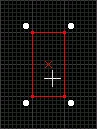
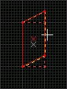
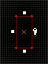
    t2pic3 t2pic4 t2pic5 c) Selector function: parallel shift
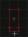
    Double-click inside an object to shift its sides parallel:
    t2pic9 t2pic10 d) Selector function : quickly create a copy of an object
    You can quickly make a copy of a selected object by simply holding down Shift , when transferring it. This is a very convenient function that significantly simplifies and speeds up the process of creating a map. It is very convenient to make walls, fences or boxes in this way: make 1 wall, and then with a clamped Shift, copy.
    Copying objects using Shift is much more convenient than using the clipboard (Copy -> Paste), because from the buffer, the object is inserted into the origin or the center of the screen, which is often inconvenient. When copying by dragging, the object is created at the same height as the original object (in general, try it - you will like it :)
    e) Selector function: Select multiple objects
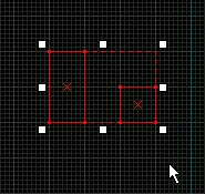
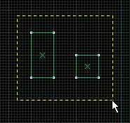
    This is probably not a function, but still, don't forget that you can select several objects at the same time, just hold down the left mouse button and select the desired objects with a rectangle, then release the button (see the figure below). Voila! All objects are selected. By the way, the same result can be achieved by selecting objects one by one while holding down the key Ctrl. In general, all the principles of working in Windows apply in the editor.
t2pic11 t2pic12 2. Magnify (Loop tool)
t2wcinstr2 With a magnifying glass, in principle, everything is clear - it increases/decreases the scale of the coordinate grid. Clicking the left mouse button increases, right click decreases. If the object being edited is small, we increase the scale, and when, for example, you need to select several objects and they do not fit on the screen, we decrease the scale.
Let's say right away that you won't be using a magnifying glass :), because it's much more convenient and faster to press "+" And "" on an additional keyboard layout. You can also use the numbers 1, 2, 3 ... 0, but this is also not convenient, so remember the "+" and "–" on the additional keyboard layout.
3. Camera (Tool camera)
t2wcinstr3 The camera tool is used to create viewpoints on the map being created. Of course, you can fly around the map while editing it, but if it is large, then flying from one end to the other is a tedious task. In this case, it is easier to make several viewpoints (cameras) in different parts of the map.
Let's take a look at how viewpoints are created. For convenience, let's set the map to a top view (2d top), select the camera tool, and hold Shift and with the left mouse button draw a line.
This is what we get:
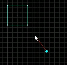
t2pic14 The turquoise dot shows the position of the camera, and the red line shows where it is looking. You can make as many cameras as you like. Remember that you can only move between cameras in a 3D view when the Camera tool is selected.
By the way, you can navigate in the 3D view of the editor after pressing the "Z" button using the usual "W", "A", "S", "D" keys and the mouse.
  • PageUp / PageDown — next/previous camera;
  • Delete — deletes the current camera.
Make it a rule: started a new map - be sure to create at least 1 camera. This is necessary so that the overview in the 3D editor view is not reset to the origin. If there are no cameras, the 3D view will constantly move to the origin, and then you will have to fly to the edited location again to see the changes. All this applies to a configuration with 1 editing window. If you use 4 editing windows at the same time, you don't have to do everything described.
And also about installing cameras. There is no need to accurately set the camera position, accurate to millimeters or degrees, because when you move in a 3D view with the camera tool turned on, the position of the current camera also moves.
4. Entity tool (Entity Tool)
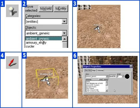
t2wcinstr4 Tool Entity Tool used to insert point entity objects onto the map (sounds, player birth points, light sources, some types of triggers, etc.). If you don't know what an entity is, read about it in the section "Entity".
How to insert an entity on a map?
Select the entity tool, and the cursor will change from an arrow to a hatchet:
t2pic16 Before we insert an entity onto the map, we need to select its type. This is done in the "New Objects" panel (the panel is located on the right). From the list of available objects, select the one you need. This list contains only point entities.
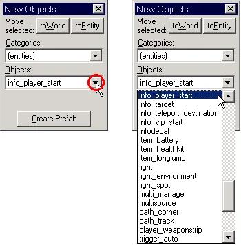
t2wcinstr entity A point entity can be inserted either in a 3D view or in any 2D view. In the 3D view, you simply click on the ground or wall and the object will be inserted. It can then be moved to another location.
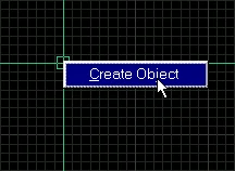
In the 2D view of the editor, by left-clicking we determine the location of the object, but it has not yet been created. We can move the green square (this is what the created point entity object looks like) in any 2D editing view, achieving the position we need. We complete the creation of an object by right-clicking on the green square and selecting the only item "Create object" in the menu. Or, without calling up the menu, you can click on Enter.
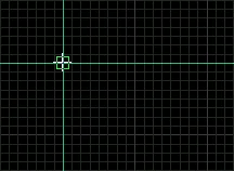
t2pic17 t2pic18 Thus, all point entities (sounds, lights, sprites, etc.) are installed.
5. Block tool (Tool block)
t2wcinstr5 The block tool is used to create brushes or brush entities. The earth, walls, mountains, water, cars, boxes and even the sky - everything is created by this tool. If for some reason you don't know what a brush is :), read about it in the article Basic Mapmaking Terms.
When you select a block tool, the cursor changes to a frame:
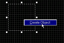
t2pic19 To create a regular rectangular brush (wall, box, floor), you need to hold down the left mouse button, set the size of the rectangle, and release the button. Brush is not ready yet (similar to the creation of a point entity object). Now we can change the size of the future brush and set its position.
Then, as in the case of point entities, right-click (inside the brush being created) and select "Create object" from the menu, or click instead Enter (see picture below).
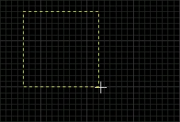
t2pic20 t2pic21 Brush is ready! Brushes are painted in different colors. Grouped brushes are painted with the same color (we'll talk about grouping objects a little later in this article). To turn a brush into a brush entity object, you need to click [Ctrl-T] and select the required object type from the list (everything is the same as in the case of point entity objects, only different tools are used).
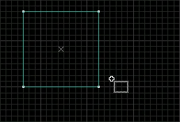
t2pic22 Naturally, no one forbids us to change its shape or move it after creating a brush - this goes without saying.
6. Texture application (Applying textures)
t2wcinstr6 A tool for applying textures, i.e. for coloring the map. When you select this tool, the cursor changes to an arrow with a bucket (see figure below).
t2pic23 You can get all the necessary information about texturing objects from the fourth section of the Tutorial - "Textures and Decals".
7. Apply Texture
t2wcinstr7 This tool is used to paint all sides of an object with the selected texture at once. For example, we selected a box and the texture of the box, we paint over one side of the box with this tool, and all the others are also painted over.
Let's say right away that there is a much more convenient way to paint all the edges of an object at once. Select a regular tool for painting (the sixth one in this review), hold down Shift and paint only 1 side - all the others are also painted over.
8. Decals (Applying decals)
t2wcinstr8 The tool is designed for applying decals over regular textures. Let us remind you that decals are also textures, but they can be applied on top of regular ones. Bullet holes on the walls, traces from grenade explosions - these are all decals.
You can get all the necessary information about decals from the fourth section of the Tutorial - "Textures and Decals".
9. Clip tool (Clip Tool)
t2wcinstr9 Tool Clip used to cut objects into pieces. The operation of this tool is described in detail in the article. Clip Tool: Cutting Objects.
10. Vertex Manipulation (Vertex Tool)
t2wcinstr10 Tool Vertex used to change the shape of objects by changing their vertices. For example, a cube has 8 vertices, if we connect the 4 top vertices to one point, we get a pyramid. This tool is indispensable when creating mountains, tunnels, and generally more complex objects than simple blocks.
The operation of this tool is described in detail in the article. Vertex Manipulation: Changing Object Shapes.
11. Path (Path Tool)
t2wcinstr11 The Path tool is designed to create trajectories for monsters. There are no monsters in CS, so we won't dwell on it in detail.
2.5

Hammer Menus

In this article we will get acquainted with the editor menu and look at what each item means.

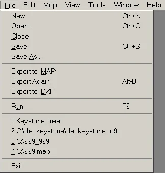
1. File menu

t2wcmenu1 New — start a new map;
Open — open a map in *.rmf or *.map format;
Close — close the card;
Save — save the map;
Save As — save the map with the extension *.rmf or *.map;
Export to Map — save the map in *.map format;
Export Again — if the map has already been saved in *.map format, then when you select this item, the editor will overwrite the previously saved file;
Export to DXF — saves the map in *.dxf format for use in 3DS Max (a program for creating 3D animation, used to create animated scenes in Half-Life). But Hammer will not be able to open a file with the extension *.dxf;
Run — opens a window with map compilation parameters.

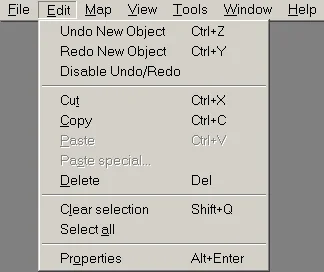
2. Edit menu

t2wcmenu2 Undo — undo the last change (the number of possible undoes is set in the "Tools\Options\General\Undo Levels" menu);
Redo - the opposite of Undo;
Disable Undo/Redo - do not use Undo/Redo;
Cut, Copy, Paste — cut, copy, paste an object from the clipboard;
Paste Special — allows you to paste several copies of an object from the buffer;
Delete — delete the selected object;
Clear Selection — deselect the object;
Select All — select all visible objects on the map;
Properties — shows the properties of the selected object.

3. Map menu

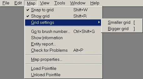
t2wcmenu3 Snap to grid — snapping an object to a coordinate grid, i.e. the object moves along the grid cells;
Show grid — show the grid;
Grid settings — sets the grid cell size, shortcut keys "[" and "]";
Go to brush number... — allows you to go to a specific brush or entity by number, useful when ZHLT compilers give an error and the number of the object that caused it;
Show Information — shows the total number of objects on the map, the number of entities, the number of sides of objects (faces), non-standard textures, memory used by textures, connected WAD files;
Entity report... — shows a list of all used entities on the map with the ability to view object properties, go to the object for editing, etc.;
Check for Problems — looks for errors on the map, but some of them can only be detected during compilation;
Map properties — opens a window where you can set some parameters for the entire map, such as: name of the sky picture, minimum illumination level, maximum visible distance, etc.;
Load Pointfile — load a *.pts or *.lin file into a 2d view with the "LEAK" error, if one occurs during compilation;
Unload Pointfile — closes the above files.

4. View menu

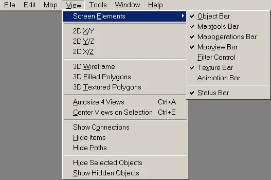
t2wcmenu4 Screen Elements — here you can show or hide this or that editor panel;
2D X/Y; Y/Z; X/Z — switching between 2D editing types;
3D ... — switching between 3D editing types;
Autosize 4 Views — equalizes the size of editing windows when using 4 windows;
Center Views on Selection — aligns the selected object to the center of the screen, "Ctrl-E";
Show Connections — displays in 2d projections lines connecting action objects and goal objects (for example, a switch and a light bulb);
Hide Items, Hide Paths - the first point hides point entities, and the second - the paths along which monsters move;
Hide Selected Objects — hides selected objects;
Show Hidden Objects — shows hidden objects;

5. Tools menu

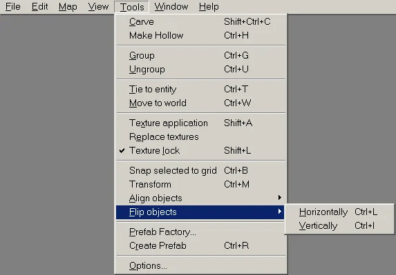
t2wcmenu5 Carve — a utility that allows you to cut holes of various shapes in objects, read more in the article Creating Holes with Carve;
Make Hollow — makes the selected objects hollow, while you only set the wall thickness: positive or "negative", read the article for more details Creating Hollow Objects with Hollow;
Group/Ungroup — groups/ungroups selected objects;
Tie to Entity — turns the selected brush into a brush entity object;
Move to World — turns a brush entity object back into a brush;
Texture application — opens the panel for working with textures;
Replace textures — replacing one texture with another;
Texture lock — fixes textures on objects; when an object is rotated or displaced, the textures on it do not move (be sure to enable this option!);
Snap selected to grid — aligns the selected object to the grid cells;
Transform — allows you to rotate, scale and move objects, "Ctrl-M";
Align objects — allows you to align an object in different directions;
Flip objects — mirrors objects relative to vertical or horizontal axes;
Prefab Factory... — allows you to create and edit prefabs (blanks) stored in *.ol files;
Create Prefab — create a prefab from selected objects;
Options... - editor settings, Installing and Configuring Hammer;

6. Window Menu

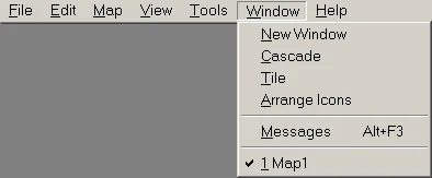
t2wcmenu6 New Window — open a new editing window;
Cascade — arrange windows;
Tile — place editing windows on the screen;
Arrange Icons — arrange the icons of minimized windows;
Messages — shows a window with errors (if any) during the FGD file loading process;

7. Help Menu

t2wcmenu7 Help Topics — help (in English);
Web Resources — links to various sites about mapping;
About — information about the editor version;
The dimensions of objects, cursor position, and grid spacing are indicated in the help line (see the figure below).
t4helpline Well, this completes the description of the editor menu items. If something remains unclear to you, don't despair! In subsequent articles of our Tutorial we will talk in more detail about the use of certain editor functions. Moreover, we are still studying theory, the most interesting thing is ahead - practice!
2.6

Dimensions and Scale

This is one of the most important articles for a novice mapper, which will help you understand what size objects need to be created so that they appear real. For example, how high should the wall be so that it is equal to the 1st floor or how high should the door be so that the player can pass through it, etc. You will also learn about the maximum possible card sizes.

Units of measurement in Half-Life and the editor

Dimensions (length, width, height) and distance in Half-Life are measured in units (unit) - a certain virtual unit of measurement of length. The dimensions in the map editor are also measured in units, which allows you to see the map as it will be in the game.
The minimum unit of length, height and width is 1 unit. This means that the smallest object on the map can be 1x1x1 units in size.

Maximum map size in Half-Life

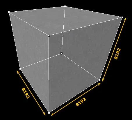
In Half-Life, the maximum map size can be 8192х8192х8192 unit. This is exactly the size of the workspace in the map editor. This space can be represented as a cube with a side of 8192 units (see figure below).
Map editor workspace size
At the center of this imaginary cube is the origin, which is indicated by colored perpendicular lines in 3D views and green in 2D views. Usually, the map begins to be built near the origin of coordinates, i.e. in the center of the cube.
To compare the maximum possible size of a map with existing known maps, we give several examples.
Map De_aztec
  • Length: 6032 (counting from base CT to T)
    Width: 3392
    Height: 1760
Map De_Dust
  • Length: 6208 (counting from base CT to T)
    Width: 5648
    Height: 896
From the examples given, it is clear that in length these maps occupy ~75% of the space, in width: 41% (Aztec) and 68% (Dat), in height: 21% (Aztec) and 10% (Dat). Based on this data, we can conclude that typical maps take up 55 to 65% of free space.

Creating objects of the required size

The size of objects in the editor is very easy to control by cell. But first you need to determine the grid pitch (the size of each cell). You can view it in the status bar, on the very right side, after the word "Grid:".
t4helpline For example, Grid: 16 means that the grid spacing is 16 units. Increasing/decreasing the grid step is carried out using the buttons "[" And "] " Remember these buttons, you will use them often.
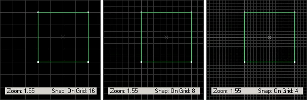
The figure below shows how this function works: the grid step decreases, but the zoom remains constant. This function is needed to more accurately determine the size of an object. For example, if we need to make a box of 64 units, then it is convenient to set the grid step to 16 units and count 4 cells. If you need to make a side with a height of 24 units, then it is more convenient to set the grid step to 8 units and count 3 cells, etc.
t2sizegrid16 8 4 Now let's look at the second function that controls the appearance of the mesh - this is zoom. Everything is simple here: the grid step is the same, but the image is simply enlarged (decreased). To change the zoom, use the "+" and "–" buttons on the additional keyboard.
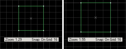
t2sizezoom The grid spacing and other parameters can be changed in the "Options/2D views" menu (see figure below).
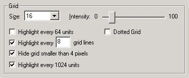
t2wcopt21 Well, now you know how to control the coordinate grid and measure the sizes of objects.
Examples of sizes on maps

So let's go back to units . What can a real life unit be compared to? Most likely, with an inch (2.54 cm), but no one will give you an exact answer (maybe only at Valve :) Our guess can be indirectly confirmed by the height of the player in Half-Life, which is 72 units or, translated into centimeters, 180 cm, which is quite comparable to the height of a person. By the way, the height of the player in CS is slightly less - 64 units or 160 cm, which is clearly not enough for a special forces soldier :)))
Now here are some examples showing the different sizes on the maps.
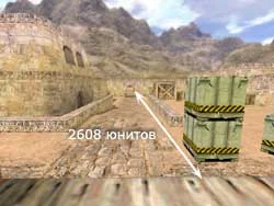
To begin with, it would be nice to see what the maximum distances are on standard maps (take Aztec and Dust). The example below should stop you if you want to make the open space more than 2600 units :) Simply, too large open spaces deprive the map of strategicity, turning it into an AWP arena.
De_Dust. Length of passage from control base
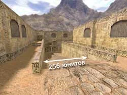
Width of descent under the bridge (256 units):
De_Dust. Bridge descent width
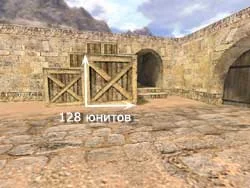
Box size at the entrance to the intestine (128 units):
De_Dust. Size of the box at the entrance to the intestine
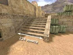
Step width on T base (224 units):
De_Dust. Step width based on T
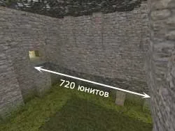
Aztec Bridge Length (720 units):
De_Aztec. Length of the Aztec Bridge
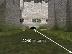
Distance in water (2240 ​​units):
De_Aztec. Distance in water
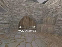
Gate width (256 units):
De_Aztec. Gate width
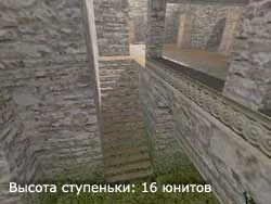
Step height (16 units):
De_Aztec. Step height

Dimensions of standard objects

For frequently encountered objects such as doors, stairs, windows, etc., more or less standard (or better yet, optimal) sizes are defined, which are perceived in the game as real.
1. Doors (doorways)
Door 96x64x8 Height: 96
Width: 64
Thickness: 4-8
2. Windows (window openings)
Window 64x48 Height: 64
Width: 48
3. Stairs
Staircase: width - 32, thickness - 4 Width: 32
Thickness: 4
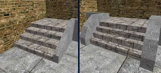
When building ordinary stairs, the height of the step is made equal to 16 units (if more, the player will not be able to climb onto it without jumping), and the length is 16-32 units (see the figure below).
Stairs. Step height - 16; step length - 32 (left) and 16
4. Boxes
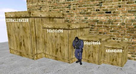
The figure below shows the main dimensions of boxes with sides of 128, 96, 64 and 48 units compared to a player with a height of 72 units (in CS the player is 64 units, i.e. his height is exactly equal to the height of the second box from the right).
Boxes from 48 to 128 units
5. Other
The thickness of the walls is usually 16-32 units;
The height of a standard room is 128-144 units.

Gameplay dimensions

When building maps, it is necessary to take into account not only the proportions and sizes of objects so that they do not seem too large or too small to us, but also the sizes that affect the gameplay. For example, if the distance between two walls is not large enough, then the player will not be able to pass between them, or, in the second example, the distance between the roofs of the houses is too large, then the player may crash without jumping enough.
Below we present the main gameplay dimensions for Half-Life.
Note: for CS the data on the maximum jump distance is smaller.
The height of the obstacle that the player can overcome without jumping:
(such an obstacle could be the steps of a staircase or a side)
  • standing: 18 units
  • sitting: 18 units
The minimum height between the ground and an object that allows the player to pass:
(this could be door or window openings, a ventilation shaft, a hatch, etc.)
  • standing: 73 unit
  • sitting: 37 units
The minimum distance between objects that allows the player to pass between them:
  • 33 unit
The maximum height of an object that a player can jump to:
  • standing: 44 unit
  • sitting: 44 unit
  • standing, holding "Ctrl" (long jump): 62 unit
Maximum jump distance on a flat surface:
  • sitting: 99 units
  • walking: 109 units
  • running: 239 units
  • run while holding "Ctrl" (long jump): 259 units
Damage received by a player when falling from different heights:
  • 128 units - 0%
    192 units - 9-10%
    256 units - 27-28%
    320 units - 43-44%
    384 units - 57-58%
    448 units - 70-71%
    512 units - 82-83%
    576 units - 93-95%
    640 units - 100% Death :)
2.7

How to Work Better in Hammer?

In this article we will give some useful tips that will help you quickly master the editor and speed up your work in it.
Contents of the article:
  • Window configuration
  • Types of editing
  • Types of 3D Editing Views
  • Using the 3D textured view
  • Direction of coordinate axes in 2D views
  • Navigate the map in 3D views

Window configuration

There are TWO window configurations:
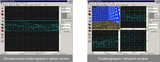
  1. Independent (1 editing window)
  2. Configuration with 4 editing windows
When you first launch the editor, either four or one editing window will appear in front of you, depending on the selected configuration (see the figure below).
Two different editing window configurations
The configuration can be changed in the "Tools\Options\General" menu. If the checkbox opposite "Use independent window configuration" is checked, then you will have one editing window; if not, four. After changing the configuration, restart Hammer or simply close all maps you are editing and reopen them.
Which configuration is more convenient?
You will determine which configuration is more convenient after working a little with the editor. With an independent configuration, when there is one editing window, more workspace is visible and the object can be zoomed in more (meaning that with more visible space, you will see more of the zoomed-in object) than when using 4 windows. Therefore, from our point of view, one editing window is more convenient, although at the same time we are forced to switch between types of editing.
When using four editing windows there is no need to switch between editing types, but the windows are quite small and very little of the map is visible. However, if you use large diagonal monitors (19", 21" and larger), then this configuration may be more convenient. The window in which the cursor is located is considered active, that is, if the cursor is located above the upper right window, then all editor functions, for example, zooming, will work in this editing window.

Types of editing

The Hammer editor has six various types of editing:
  • 2D top (x/y) - 2D top view
  • 2D front (y/z) - 2D front view
  • 2D side (x/z) - 2D side view
  • 3D wireframe - 3D view (object edges)
  • 3D flat - 3D view (object edges)
  • 3D textured - 3D view (objects are textured)

Types of 3D Editing Views

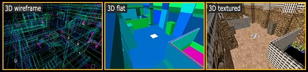
The types of all available 3D editing views are shown in the figure below:
3D views: wireframe, flat, textured
In the form 3D wireframe wireframes (edges) of objects are displayed.
In the form 3D flat objects are displayed without textures and each individual brush has its own color, different from its neighbors. This view is convenient to use to detect brushes that have been unnecessarily cut into pieces, for example, when two brushes can be replaced with one.
In the form 3D textured You can see approximately how your map will look in the game (only without calculated lighting). It is also convenient to create point entity objects in this view (see below), select objects and move them using the keyboard arrows.

Using the 3D textured view

View 3D textured, perhaps the most commonly used of the 3D editing types, because... it is in it that textures and decals are applied to the map, and it is also convenient to create point entity objects (for example, sounds, places of birth of players, light bulbs, point triggers, etc.). Next, we show a picture and describe the steps from creating a point entity object to calling its properties.
To create a point entity object in a 3D view:
  1. Select the "Entity Tool"
  2. Specify the type of entity to be created in the "New Objects" panel
  3. Click in 3D view on the wall or ground
Create a point object in 3D view
To call the properties of an entity object:
  1. Select (select) an entity object
  2. Press "Alt-Enter"
  3. In the window that appears, you can change both the properties of the object and its type

Direction of coordinate axes in 2D views

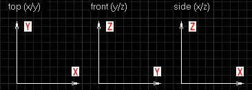
When creating various rotating objects (fans, platforms, trains, cars), you need to know the directions of the coordinate axes. With the Z axis everything is simple, in the 3D view it is always directed upward, perpendicular to the ground, but with the X and Y axes it is more complicated.
The figure below shows the direction of the axes in each of the 2D editing views.
t4howork1

Navigate the map in 3D views

In any of the 3-dimensional editing windows you can navigate around the map being created.
"Z" - transition to moving around the map (one more press - exit this mode);
"W", "S", "A", "D" - forward, backward, left, right;
If, when you press "Z", you cannot get into flight mode on the map, then you have the Russian keyboard layout enabled :) Just switch to English and everything will work.
We recommend that you read one of the following articles in this chapter about editor keyboard shortcuts, because some of them will significantly speed up and facilitate the process of creating a map.
2.8

Checking a Map for Errors

In this article you will learn how to check a map for errors in the map editor. We will also talk about the most common errors and how to fix them.
Checking the map for errors is carried out using the keys [Alt-P]. We recommend that you check your card for errors frequently so that you can take action in a timely manner.
Unfortunately, not all errors are detected in the map editor. Many of them (often more insidious :) appear only during compilation. But there's nothing wrong with that, because... ZHLT compilers have a detailed error reporting system, which allows them to be quickly found and corrected.

The most common errors when creating maps:

  1. There is no player start
  2. Invalid texture (texture name)
  3. Texture axic perpendicular to face
  4. Invalid solid structure
  5. Solid entity (object name) is empty
  6. Unmatched 'target' field (name)
  7. Mixed face contents
  8. Entity (object name) has unused keyvalues
  9. Entity (object name) contains duplicate keyvalues
  10. Invalid solid contents
  11. Solid contains duplicate planes

1. There is no player start

There are no player birth points created on the map. To fix the error, create one or more objects "info_player_start" and "info_player_deathmatch" (contra and terrorist spawn points, respectively).

2. Invalid texture (texture name)

The error means that an object or several objects do not have a texture. You can go to erroneous objects using the "Go to error" button in the error correction window. The object causing the error will be completely white.
This error may occur if no textures were found as a result of the wad file being disabled. To fix the error, you need to either connect a wad file with the textures specified in the error, or paint over the object with some other texture.
Also, the same error always occurs if you select one wad file from the list and build objects. Then you switch to another wad file from the list and continue building objects, forgetting to select a texture from the new wad file. That is, it turns out that you changed the wad file, but the old texture name is used.

3. Texture axic perpendicular to face

This error occurs for two reasons:
  1. If you rotated an object with the option turned off "Texture lock", and the texture became perpendicular to the side of the object;
  2. There is an irregularly shaped object on the map resulting from vertex manipulation or using the Carve function.
In both cases it is easier to delete the object and create a new one.

4. Invalid solid structure

The error means that there is an irregularly shaped object on the map resulting from vertex manipulation. Try to fix this object or delete it and create a new one.

5. Solid entity (object name) is empty

The error means that the brush entity has no shape (that it is empty). It is difficult to say why this error occurs, but it has been noticed that sometimes an entity object itself becomes a brush, and the editor still considers it an entity object. And when we re-convert the brush into an entity object, this error occurs. So, most likely, this is due to glitches in the editor itself. In any case, it is better to get rid of such errors, although they do not affect the compilation in any way.
And it's pretty easy to get rid of. Click [Alt-P], in the window that appears, highlight the line "Solid entity ... is empty" and click the "Go to error" Look at the size of the object (in the status bar) if you see something like: -1999998w, then press Delete (i.e. just delete this object). Do the same with other "empty" objects.
Note: when you go to an "empty" object, it will not be visible on the map, but the editor still goes to it and allows you to delete it.

6. Unmatched 'target' field (name)

The error means that the "Target" parameter that caused the object error contained the name of a non-existent object. To correct the error, go to the object with the "Go to error" button and delete/correct the entry in the "Target" parameter, or create an object with the name specified there.
The following case can be cited as an example. You have created a button that turns on a light bulb. In the "Target" parameter, the buttons indicated the name of the light bulb, but they forgot to make the light bulb itself. In this case, the error discussed above appears.

7. Mixed face contents

And this is a constant mistake of those novice mappers who do not want to read our articles about the types of textures in Half-Life :) The error means that you painted some of the objects with incompatible types of textures, for example, you painted several sides of the object with a regular texture, and others with a water texture. Read the article Texture Types in Half-Life and CS and then you can easily correct this error.

8. Entity (object name) has unused keyvalues

The specified object contains parameters that are not used in its class. The error can be corrected with the "Fix" button.

9. Entity (object name) contains duplicate keyvalues

The specified object contains several identical parameters. The error can be corrected with the "Fix" button.

10. Invalid solid contents

See error 7. "Mixed face contents" above.

11. Solid contains duplicate planes

The error means that some object has two planes superimposed on each other. To correct the error, click the "Go to error" button, delete the object and create a new one.
2.9

Hammer Keyboard Shortcuts

In this article we provide a complete list of Hammer editor hotkeys. Usually, the desire to speed up your work in the editor appears when you feel that you have become familiar with it. However, it will be useful to simply look at this list. Perhaps you will remember some useful combinations now.
In a word remember We've highlighted the most useful keyboard shortcuts. It's better to write them down on a piece of paper and memorize them like a multiplication table :)

Tools:

  • Shift-S — Object selection tool
  • Shift-G — Changing the grid scale
  • Shift-C — Camera control in 3D editing views
  • Shift-E — Tool for creating point entities
  • Shift-B — A tool for creating brushes, brush entities and prefabs
  • Shift-A — Texturing objects
  • Shift-T — Applying the current texture to all sides of the selected object
  • Shift-D — Applying decals over textures
  • Shift-X — Cutting objects (as well as choosing a cutting mode) remember
  • Shift-V — A tool for manipulating object vertices (as well as selecting a mode)
  • Shift-P — Path tool for creating paths for monsters (not used in CS)

Clipboard/item selection:

  • Ctrl-C — copy object to clipboard (also Ctrl-Insert)
  • Ctrl-V — insert an object from the buffer onto the map (also Shift-Insert)
  • Ctrl-X - cut objects to buffer (also Shift-Del)
  • Ctrl-E — place the selected object in the center of the editing screen remember
  • Shift-Q - remove selection
  • PgUp — the previous object in the "hit list" (what is it :)
  • PgDn — the next object in the "hit list" (similar to :)

Net:

  • [ — reduce the grid step by 2 times remember
  • ] — increase the grid step by 2 times remember
  • Shift-R — enable/disable grid display
  • Shift-W — enable/disable snapping of objects to the grid
  • P — (when the cursor is in the 3D view) turn on/off the grid in the 3D view

Grouping objects:

  • Ctrl-G — group selected objects remember
  • Ctrl-U — ungroup a group of objects remember

Carving/Hollowing:

  • Ctrl-Shift-C - Carve function remember
  • Ctrl-H - Hollow function remember

Creating objects:

  • Enter - create an object
  • Alt-Shift-C - insert prefab
  • Ctrl-R — create a prefab from selected objects
  • Ctrl-T — turn a brush into a brush entity object (if you need to add a brush to an existing entity object, for example, some piece to a door, then select both the entity and the brush to be added and press "Ctrl-T", answer "Yes" to the question) remember

Other operations with objects:

  • Ctrl-B — align selected objects to the grid remember
  • Alt-Enter — calling properties of selected objects remember

Working with files:

  • Ctrl-N - create a new map
  • Ctrl-O — open the map
  • Ctrl-S — save the map

Cancel actions:

  • Ctrl-Z — cancel the last action (the number of possible cancellations is set in the options)remember
  • Ctrl-Y - the opposite of the previous command remember

Actions in 2D view:

  • Ctrl-I — vertically flip the selected object remember
  • Ctrl-L — horizontally flip the selected object remember
  • Tab — switching between 2D editing views (top/front/side) remember
  • + And - — zoom in/out (holding "Ctrl" will change the scale synchronously in all 2D views)
  • Numbers 1 - 9 - preset zoom levels
  • Space — hold down the space bar and the left mouse button to move around the editing window
  • Alt — removes the snapping of an object to the grid when pressing "Alt" and dragging with the mouse

Actions in 3D view:

  • Z — transition to moving around the map in 3D view remember
  • W - forward
  • S - back
  • A - left
  • D - to the right
  • P — turns on/off the grid in 3D view
  • O — shows the number of frames per second and camera angles

Working with vertices (vertices) of objects:

  • Ctrl-F — dividing the plane into two when manipulating the vertices (vertices) of an object remember
  • Alt-E - vertex scaling

Selecting objects:

  • Ctrl - hold down "Ctrl" and click on objects one by one to select them remember
  • Shift — hold down "Shift" when rotating an object, then it will rotate 15 degrees or, conversely, smoothly (depending on the properties set in the "Options\2d views" tab).
    Hold "Shift" while dragging an object to make a copy of it remember

Camera Tool:

  • Shift — the camera is created by moving the left mouse button while holding down the "Shift" key remember
  • PgUp — go to the next camera
  • PgDn — go to the previous camera
  • Delete — delete current camera

Cutting objects:

  • Enter — complete cutting the object remember
  • Ctrl — while holding "Ctrl", moves the cut line (both points at the same time)
  • Shift — while holding "Shift", a new cutting begins, regardless of the already established points by which the cutting line is determined remember
  • O — show/hide dimensions when cutting an object (in 2D view) remember

Miscellaneous:

  • Alt-B — export the map to MAP format again (if the map has already been exported before)
  • Ctrl-A — auto-align to the center of four editing windows
  • Shift - hold down "Shift" when applying the texture, then it will be applied to all sides of the object remember
  • Shift-L — turns on the binding of textures to the object (must always be turned on!)
  • Shift-Z — maximize/restore view
  • Ctrl-M — object transformation dialog (scaling, rotating, moving)
  • Alt-P — check the map for errors remember
  • F9 — map compilation dialog/start compilation
  • Escape — cancel the current operation (when moving an object)
2.10

Extracting Resources from pak0.pak

All sounds, models, sprites and levels of Half-Life are stored in a special archive pak0.pak. This archive is located in the valve directory. How can this archive be useful to us and why unpack it?
It's very simple. The contents of the pak0.pak archive can be useful in many cases. For example, we decided to create fire on the map. For this we will naturally use an animated sprite. A wonderful fire sprite can be found in this archive. But the problem is that the Hammer editor cannot read files inside the archive; it can only access ordinary folders and files.
In this case, you need to pull out the sprite, put it in the desired folder (in the case of a sprite: "cstrike\sprites") and then in the editor, in the object properties, specify the path to the sprite.
You can extract files from the pak0.pak archive using programs such as Wally (see below), PakExplorer, PakScape. Download links can be found in the section What Programs Are Needed to Create Maps?.

Unpacking a PAK archive using Wally

Let's look at exporting files from the pak0.pak archive using Wally. Everything here is extremely simple.
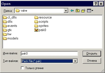
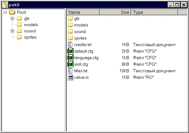
Let's launch Wally. Click Ctrl-O and in the list indicate the type of file to open (*.PAK). Go to the directory with Half-Life installed in the valve folder. Open the pak0.pak file.
t4pak0pak0 A window resembling a conductor will appear in front of us. On the left are folders in the archive, on the right are files in these folders. First of all, we are interested in folders sprites, sound, models (sprites, sounds, models).
t4pak0pak1 Select the required files, right-click and select "Export":
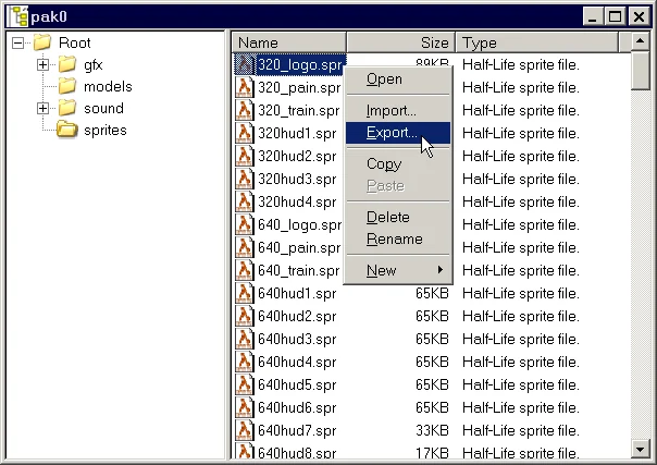
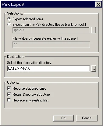
Export the selected files to a temporary directory
In the next window you need to specify the folder where to extract the files (for us it is "C:\TEMP\PAK").
t4pak0pak3 Here's what the rest of the options mean:
Export selected items
Extract selected files.
Export from this PAK directory
Extract all files from the specified directory.
File wildcards
Extract the specified file formats (specify separated by a space, for example, *.spr *.wav).
Recurse Subdirectories
Process subdirectories.
Retain Directory Structure
Maintain folder structure.
Replace any existing files
Replace (overwrite) any existing files.
Note: You can listen to sound files from the Sound folder by double clicking on them.