Chapter V. First Practical Lessons.

Hands-on lessons: brush creation tools (clip, carve, hollow, vertex manipulation), building your first map, and all CS map types.

5.1

Creating Brushes, Entities, and Prefabs

In this article we will learn how to create the simplest objects on the map, insert entity objects, and create prefabs. The article is quite long, with a lot of pictures, so be patient and read it carefully. As practice shows, novice mappers have a lot of questions when creating simple objects and performing the simplest operations on them. This article answers many of these questions.
Content:

1. Creating a brush

To create a regular brush, you need to select the Block tool [Shift-B] and the cursor will change to a frame (see figure below)
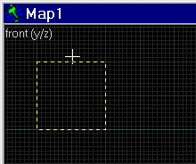
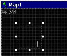
t2wcinstr5 t2pic19 Let's select the top view and, holding down the left mouse button, set the size of the rectangle, say 256x256 units and release the button. The object is not ready yet.
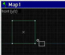
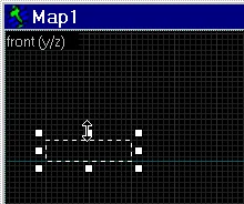
t4brush1 Let's switch to a side view or front view (it doesn't matter) and increase the height of our object to 256 units.
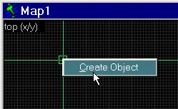
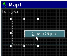
t4brush2 t4brush3 Now that the position of the object and its dimensions are set, all that remains is to hover the cursor over the object, press the right mouse button and select the only option "Create object".
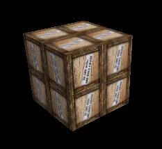
t4brush4 t4brush5 Let's see how it will look in the game, for this we will select the 3d textured view.
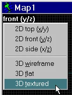
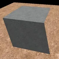
t4brush6 Brush image in 3D form
The brush in the form of a cube with dimensions of 256x256x256 units is ready. Now we can replace and align the textures on it, as well as move it to any place on our map, change the size, shape, etc.
Note: the size of the created or selected object is displayed in the help line at the bottom of the screen (see figure below).

t4helpline

2. Create an entity

All entities are divided into point-based entities, for example, light and sound sources, some types of triggers, players' birthplaces, etc., and brush-based entities, for example, triggers, buttons, doors, elevators, etc.
Point entities are inserted onto the map using the tool Entity Tool [Shift-E]. To create a brush entity, you first need to make a brush and then turn it into an entity. Example, a door. Create a brush shaped like a door and turn it into a func_door object. The transformation is carried out by a keyboard shortcut [Ctrl-T].
You can read more about entity objects and their properties in the section "Entity".
Let's look at the creation of these two types in more detail.

2.1. Creating a point-based entity object

Select the Entity Tool [Shift-E] and the cursor will change to a hatchet (see figure below)
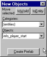
t2wcinstr4 t2pic16 Now let's turn our attention to the right side of the editor's working field. There is a New Object panel (highlighted with a blue frame).
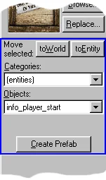
t4ent1 t4ent2 You can pull out this and any other panel as shown in the picture on the right.
In line Objects we select the type of point entity we want to insert into the map. By default, the list contains info_player_start (i.e., the birthplace of the contra). You can change the default entity type in the menu Tools > Options... > Game Configurations (see picture below)
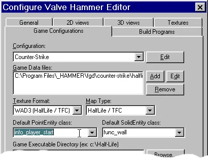
t4ent3 In line Default PointEntity class the point-based entity is installed by default, and in the line on the right, Default SolidEntity class the brush-based entity is installed by default.
Next on the list Objects select the required entity type, for example light (light source).
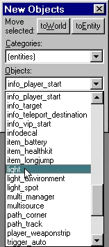
t4ent4 And insert it onto the card.
t4ent5 t4ent6 As a result, our light source will be depicted as a small purple rectangle.
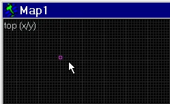
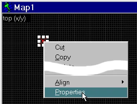
t4ent7 t4ent8 Now, if necessary, we can move our entity to another location and also change its properties. To do this, select the entity and press the right mouse button. A menu will appear with various options (picture on the right): copy, delete, group, etc. We are interested in the last line Properties. We advise you to remember the shortcut keys for object properties [Alt-Enter].

2.2. Creating a brush entity object

To create this type of entity, we first need to make a brush, and then, having selected it, select in the context menu Tie to Entity or press the keyboard shortcut [Ctrl-T].
You can turn brushes into brush entities and entities back into brushes using the buttons on the "New Object" panel. Button toEntity turns a brush into a brush entity object, button toWorld turns a brush entity object into a brush (i.e. the reverse operation).
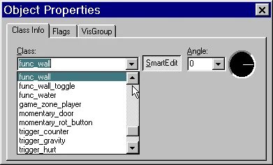
In the window that appears, we must indicate the type of entity object (select it in the list), then we can change its properties, what goes under the word Attributes.
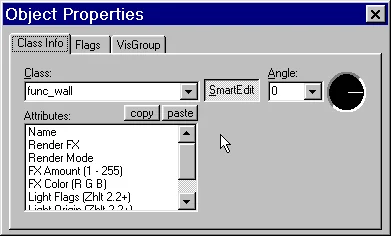
t4ent9 Selecting the entity type. t4ent10

More information

It should be noted that at any time you can change the type of an entity. To do this, select it and click [Alt-Enter] or select from the context menu Properties.
In addition to entity properties, you can set various flags (Flags tab). There are different flags for different entities. There may not be any flags at all.
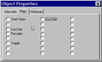
t4ent12

3. Creating and inserting prefabs

As you already know, a prefab is a template consisting of one or more objects for quick insertion into a map (for example, a chair, a bookshelf, a lamp, a box, etc.). Prefab libraries are stored in files with the *.ol extension in the "Hammer\prefabs" directory.
Hammer comes with 5 libraries with prefabs: computers (computers), crates (boxes), old stuff (sofa, several armchairs), random objects (trash, sofas, safes, etc.), usable objects (spotlight, first aid kit, etc.)
In order to insert a prefab onto the map, select the Block Tool [Shift-B], then in the panel New Objects in line Categories Let's choose one of the prefab libraries, for example, computers.
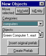
t4pref1 In the line below ("Objects") we select a specific instance of the computer, for example, Green Computer. Now click on the button Insert original prefab.
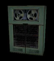
Prefab
The prefab is placed at the origin when viewing in 3D view, or at the center of the screen when viewing in 2D view.
You can also create your own prefabs. To do this, select all the objects that will make up the future workpiece and in the panel New Objects click the button Create Prefab
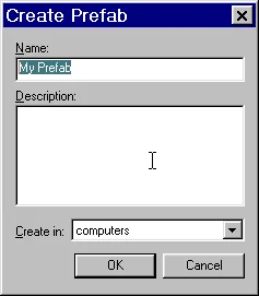
t4pref3 In the field Name indicate the name of the prefab in the field Description You can write additional information about the prefab (for example, its dimensions), and in the field Create in You select the library in which to save the workpiece.
If you do not want to save your prefab in standard libraries, you can create your own. To do this in the menu Tools select item Prefab Factory...
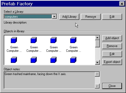
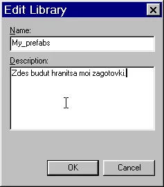
t4pref4 Then click the button Add Library, specify the name of the library, you can also enter a description for your library.
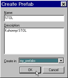
t4pref5 Now, when creating your own blanks, you can choose to save your library. For example, we made a kitchen table template and now save it in the My_Prefabs library.
t4pref6 This concludes the article on creating objects on the map.
5.2

Block Tool Shape Variants

In this article we will look at all the possibilities that the Block tool provides us.
Content: The Block tool, also known as the Block Tool, allows you to insert 5 objects of different shapes onto the map: a regular rectangular brush + 4 objects listed above in the contents of the article.
Basically, ordinary "rectangular" brushes are used to build a map, and a cylinder is often used as an additional shape. The remaining 3 types of objects are rarely used, at least they can be quickly obtained from a rectangular brush (for example, cutting it in half, we get a corner).
We described in detail the creation of a regular brush in the article How to Create a Brush, Entity, or Prefab?.
Let's now look at the creation of the other four types of objects in more detail.

1. Creating a Cylinder

To begin with, let's agree that the menu Tools > Options... > 2D views in line Reorient Primitives on creation... the checkbox is checked. Why is this needed? Read below.
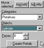
To create a cylinder, select the Block tool [Shift-B] and in the panel New Objects on the list Objects let's choose cylinder.
t4cyl1 In the field Faces we can specify the number of side faces of the cylinder ranging from 3 to 32. The more there are, the rounder our cylinder will be.
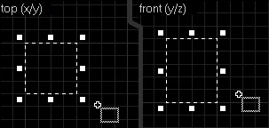
So, in the top view we will make a square measuring 64x64. Let's switch to a side or front view and make the height of our cylinder equal to 80 units.
t4cyl2 In the top view, in the right-click menu, select Create object. The cylinder is ready.
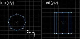
t4cyl3 Now let's explain why in the options you need to check the box next to Reorient Primitives on creation... It's easier to explain with a picture.
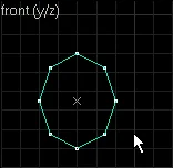
t4cyl4 If we were to use the command Create object in the form of front, then our cylinder would be inscribed in a rectangle with sides 64x80. If this checkbox is not checked, then the position of the cylinder will not depend on the selected view and the cylinder will always fit into the rectangle in the top view.
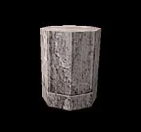
This option is convenient when we need to draw a cylinder (for example, a barrel in a game) lying on the ground. Then just click in the front view Create object and there is no need to waste time rotating the cylinder if the box was not checked.
We hope that this explanation will be clear to you. You can experiment yourself with and without the checkbox checked.
And this is what our cylinder looks like in 3-dimensional form. Quite angular, isn't it?
Cylinder in 3D view
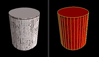
As we wrote above, in the field Faces we set the number of faces (sides). The maximum number of them is 32, and a cylinder (it can be a column or a barrel in the game) will look very nice. The figure below shows an example of a cylinder with 32 sides.
Cylinder with 32 sides
Everything would be fine, but there is one thing that should not be forgotten. We want to immediately warn you against possible mistakes. A large number of faces means a large number of polygons, and the Half-Life engine is designed for a rather large number of them. So you shouldn't create too many "barrels" in one place on the map. Or create fewer edges, for example 8-12 instead of 24.
You can read more about the problem of a large number of polygons in the articles from the section Map optimization (R_Speeds).
That's all there is to creating a cylinder.

2. Creating a corner (wedge)

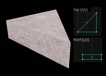
"Wedge" literally means "wedge". Externally, the object looks more like a corner. We don't think it's worth describing the construction of this type of object in particular, because it completely coincides with the construction of a regular brush. Let's just give an example with an image.
Wedge object
This type of objects is rarely used when constructing maps (meaning the use of the Block tool to create this type of objects), because it is much easier to cut off the required part from the parallelepiped to obtain a similar angle.

3. Creating a pyramid (spike)

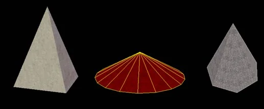
Again, the name is conditional. A pyramid is created in the same way as a regular brush. In the field Faces You can specify the number of side edges. The figure below shows several examples of such objects with 4, 20 and 7 faces, respectively.
Spike object

4. Creating spiral staircases arch

It is quite difficult to translate into Russian in one word. In general, with this tool you can create spiral staircases and similar objects. Let's look at a few examples.
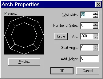
In the panel New Objects choose Arch. Create an object with dimensions 384x384x64. When you press Create object, a window like this will appear (see figure below)
t4arch1 Wall width
The thickness of an individual component, possibly a negative value, then the thickness will be counted in the opposite direction;
Number of sides
Number of parts (from 3 to 100);
Arc
The angle at which the object will be twisted (from 8 to 360);
Start Angle
This specifies the starting angle for the first part;
Add Height
This indicates the height in units by which each subsequent part will rise above the previous one. This can be used when creating twisted stairs;
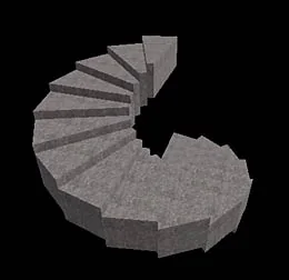
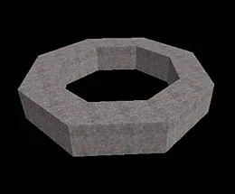
Examples of objects built by the Arch function:
Arch object exampleArch object example
You can read more about creating spiral staircases from the article of the same name: Spiral Staircases.
This completes the description of the capabilities of the Block tool.
5.3

Clip Tool

In this article we will talk about the Clip tool, with which you can cut objects into pieces.
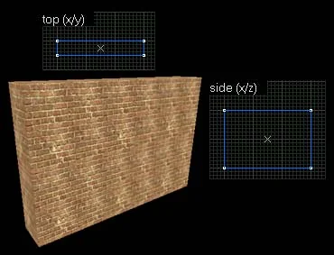
To demonstrate how the Clip tool works, let's take a part of a brick wall, a brush with side dimensions of 384x256x64
Brush with dimensions 384x256x64
Let's select the view with the largest area of ​​the wall (to make it easier to show the section) and select our object. Before using the Clip object, you must select it.
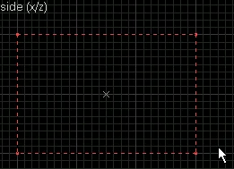
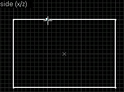
Then select the Clip tool [Shift-X] (the borders of the brush become red dotted lines) and put the first point somewhere on the outline of the brush (it becomes white). (see picture below)
t4clip2 t4clip3 Next, without releasing the left mouse button, draw a line along which our brush will be cut. To complete the operation, click Enter.
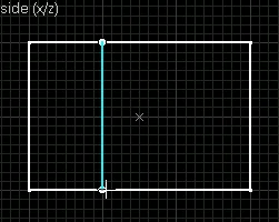
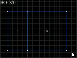
t4clip4 t4clip5 Thus, we divided the wall into 2 parts.
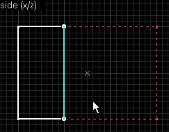
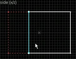
This tool has some more features. When you press again [Shift-X] we can choose which of the 2 parts to leave and which to remove.
The part that is painted white will be saved.
t4clip6 t4clip7 So when you click on [Shift-X] 3 modes of cutting an object alternate: both parts are preserved or one of the parts remains.
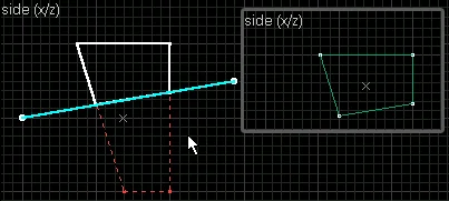
By the way, it is not at all necessary to place the points exactly on the contour of the brush (see figure below).
t4clip9 You can also cut several objects at the same time. To do this, you need to select them all and then apply Clip as usual.
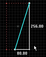
I would especially like to mention cutting brush entity objects, such as func_wall or func_breakable.
We recommend that you first turn such objects into ordinary brushes, cut them, and then turn them back into entities and set the properties. The entity turns into a brush using a button toWorld on the panel New Objects. Brush turns into an entity by clicking Ctrl-T.
If you press the "O" button while defining the cut line, the dimensions of the remaining part of the object will be displayed on the screen (see the figure below).
t4clip91 Practice cutting various objects yourself.
5.4

Carve

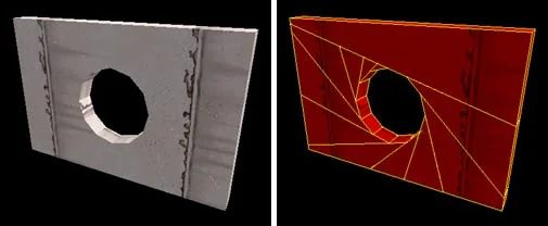
The Carve utility (function) is basically designed to create holes in walls. Why "in general"? Simply, professional mappers create all the holes using the Vertex Manipulation tool, i.e. they adjust the vertices of nearby brushes so that they create a hole. In this case, you will definitely avoid problems with poor joining of brushes, which is possible when using Carve. But since no one has banned the Carve function, you can use it to create windows, doorways, passages and the like. In this article we tell you how to do this.
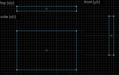
Open an editor and create a new file [Ctrl-N]. Select the Block tool and in the 2D top view, create a rectangle with dimensions of 384 units wide and 32 units high. Switch to 2D front view and lengthen the rectangle to 256 units (check all dimensions in the tooltip bar below). Finish creating the brush by pressing Enter. It should look something like this (see picture below).
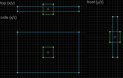
t4carve1 Now let's cut a through hole for the window in this brush. To do this, you need to create another brush, which will correspond in size to the future window, i.e. the length and width of this brush should be equal to the length and width of the future window. This brush should be placed exactly in the place where the window will be. Please note that in the top view (2D top) the new brush is thicker than the first large brush. This is done so that in three-dimensional form it is convenient to select this brush (and this will be required).
t4carve2 Switch to 3D textured view and you should end up with something like this (see picture below).
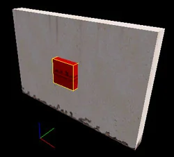
Application of Carve. Both brushes in 3D view
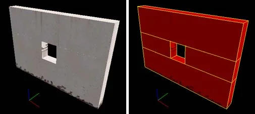
Now all that remains is to select the small brush and click [Shift-Ctrl-C] or select from the menu Tools paragraph Carve. What happened? The small brush cut out its own shape or volume, if you like, from the large brush. In principle, now we can remove the small brush as unnecessary. As a result, you should have a through hole (see figure below).
Application of Carve. Please note that when cutting a hole, a large brush is cut across its entire width (picture on the right)
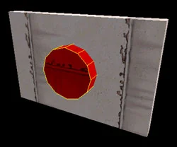
Please note that the large brush was cut completely across its entire width (picture on the right). This happens because the Half-Life engine cannot draw holes in brushes; it requires breaking such a brush into component, smaller brushes. This is why Hammer cuts the brush into smaller pieces. By the way, and this is why the Carve function is not good for use in all cases. For example, when cutting a round hole using a cylinder, the brush wall will be broken into a large number of poorly connected (thanks to Hammer :)) brushes. As a result, in the game we will get a decrease in fps (frames per second) due to the large number of brushes and poor lighting of the edges of the brushes due to poor joining.
In the picture below, we built a 12-sided cylinder to cut a circular hole in the wall.
Application of Carve. Creating a Round Hole Using a Cylinder
In the picture below, on the left, you see the final result (the finished hole), and on the right - how the brush wall is broken. In principle, you should never use Carve to create round holes due to the reasons listed above (reduced fps, poor edge lighting). Such holes, firstly, are not so often used on maps, and secondly, they are created by manipulating the vertices (vertices) of objects. We talk about this in detail in the next few articles of the Tutorial.
Application of Carve. Please note that when cutting a hole, a large brush is cut across its entire width (picture on the right)
Use the Carve function very carefully, because... If you are careless when cutting a hole, you may hit nearby objects, and they will also be cut off. When some object interferes with the cutting, temporarily move it to another place or simply hide it (there is a button on the small toolbar for this).
You can also read about the Carve function in the article "Terms".
5.5

Hollow

Using the Hollow function, we can create hollow objects, for example, from a simple cube - a room. In this article we will tell you how this is done.
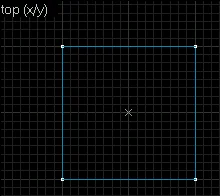
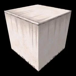
Launch the editor and create a new file [Ctrl-N]. Select the Block tool and in the top view (2D top) construct a square with dimensions of 256 units in width and height. Switch to the front view (2D front) and extend the rectangle to 256 units (control all sizes in the tooltip line below). Finish creating the brush by pressing Enter. Thus, we created a cube with dimensions of 256x256x256 units. (see picture below).
t4hollow1 Application of Hollow. Create a cube with dimensions 256x256x256
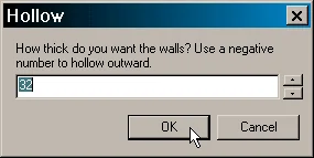
This cube is not empty inside, i.e. You can't walk inside it like you would in a room. The Hollow function is precisely used to give the cube volume, i.e. creating a cavity inside it. How to do this? Select the cube and click [Ctrl-H] or in the menu Tools select Make Hollow. The following window will appear in front of you (see figure below).
t4hollow3 This window asks what wall thickness you want to give the cube. Thickness is measured in units. Leave the default value of 32. Click OK. What happened? The cube from one brush turned into 6 separate ones that create an internal space (cavity). So we ended up with something like a room. The thickness of the walls of the room is 32 units, as we indicated. The figure below shows how our object will look in the top view after Hollow.
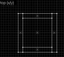
t4hollow5 The division of the cube is clearly visible in the 3D wireframe view (right).
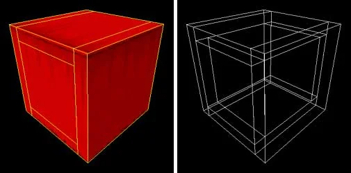
Application of Hollow. The cube broke into 6 separate brushes (3D wireframe view)
You can also specify negative values ​​in the window. For example, at -32 the cube will also be empty inside, only the walls will be placed on the outside of the cube. In this case, the internal cavity will be equal in volume to the original cube.
As with the Carve function, when using Hollow the editor does not do its best to create a brush that is empty inside. But for creating simple square-rectangular rooms, Hollow is quite suitable (at first :). In the future, when you become a little more experienced, you will understand that it is better to create a room yourself from individual brushes, using a tool for working with vertices (vertices) to reduce the number of surfaces.
And lastly, you don't need to apply Hollow to every brush on your map! Yes, this will sound funny for experienced mappers, but believe me, many novice mappers turn all the brushes on the map into mini-rooms. This is completely unnecessary! There should be no emptiness inside the brush. Imagine that the brush is an ordinary construction board. So create your level from slabs, not rooms :)
You can also read about the Hollow function in the article "Terms".
5.6

Vertex Manipulation

In this article we will tell you how to correctly use such a useful, and in some cases simply irreplaceable, tool as Vertex Manipulation, we will also look at the most common mistakes made by novice mappers who have not fully mastered this tool.
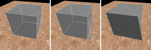
The set of objects that we can build in the editor is quite meager. It includes: a parallelepiped (as well as a cube, as its variety), a cylinder, a pyramid and an angle (half of a parallelepiped). Maps are made up of all these simple objects.
The Vertex Manipulation tool allows us to change the shape of simple objects, thus we have the opportunity to create more complex objects, such as, for example, rocks, hills, ledges, etc.
Vertexes (verteces) - object vertices (points where edges intersect)
Manipulation — changing the shape of an object by moving its vertices (vertices)
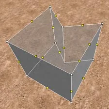
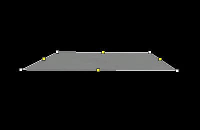
As you know from the school geometry course, a plane in space is defined by 3 points, i.e. through any 3 points in space you can draw a plane, and only one. In mapping, a plane is most often defined by four points (see figure below).
t4vertex1 Vertexes (vertices) of objects in the 3-D view of the editor are depicted as white dots, and edges as yellow. The yellow dots are placed in the middle of the edge.
Mistake #1

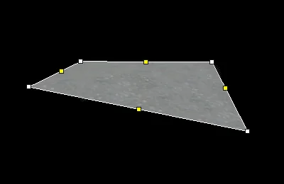
Since the number of points is often equal to four, it is quite possible that one of them will not lie in the same plane as the other 3.
Let's create a similar situation; to do this, move the right point closest to us down. As a result, our plane will have a "bend" (see figure below).
t4vertex2 Such a brush will cause an error during compilation! For the Half-Life engine, a prerequisite is that ALL points forming it are in the same plane.
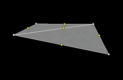
To correct this error, it is necessary to install an additional edge (see figure below).
t4vertex3 Now instead of one plane we have 2.
Moving on to specific objects, our error will look like this:
Incorrect manipulation of vertices
Often one or more sides of such an irregular (broken, as it is also called) brush seems to "disappear" (disappears). This is what it looks like in the editor:
This is what a broken brush looks like in the editor
Thus, if, after manipulating the vertices, you notice that one or more sides of the object have disappeared or are flickering in some strange way, then this brush is 100% of the wrong shape, which needs to be corrected.

Mistake #2

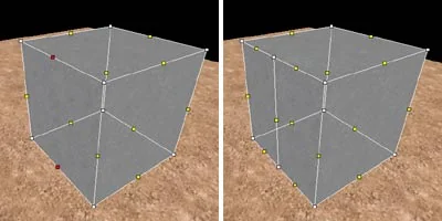
This error occurs when 2 sides of one brush lie in the same plane (see figure below).
2 sides of one brush lie in the same plane
How does this error occur? First, we highlighted the midpoints of opposite edges (they are depicted as yellow dots, and when highlighted, they are red), then we drew an additional edge (picture on the right). The edge is held by pressing [Ctrl-F].
Such an object will cause an error when compiled "coplanar plane" or in another way "Brush with coplanar faces". You can read more about this error Here.

Mistake #3

The third very common mistake is "leaf saw into leaf". It arises in a situation when the object seems to "look" inside itself (see figure below).
t4vertex7 In 3-D form it looks like this:
The object "looks" into itself (3-d view)
This is also an unacceptable situation for the Half-Life engine. How can I check that this error does not exist? Very simple. Mentally draw a plane through each side of the object; if it DOES NOT CROSS the object in any part, then there is no error. If there is an intersection, it means an error.
In fact, if we draw a plane through one of the upper faces (see figure), then it will intersect our object, and this is unacceptable!
And the way out of this situation is simple - replace one brush with two, as shown in the figure below.
t4vertex9 During compilation, this error does not always appear (the map can be successfully compiled to the end), but in the game the brush will have an incorrect shape, some of the edges may disappear (as happens with error No. 1).

Mistake #4

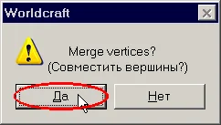
Name of this error "Plane with no normal". It occurs when you combine two vertices at one point and the question "Merge veteces?" (i.e. "Match the vertices?") answer "NO". It turns out that two points of the same face have the same coordinates (that is, they are located in the same place in space), and this is unacceptable.
Therefore, to ensure that this error never occurs to you, always answer "YES" to this question.

Varieties of manipulation with vertices

t2wcinstr10 So, we introduced you to the main mistakes. Now you know what NOT to do. Here's what you can do :)
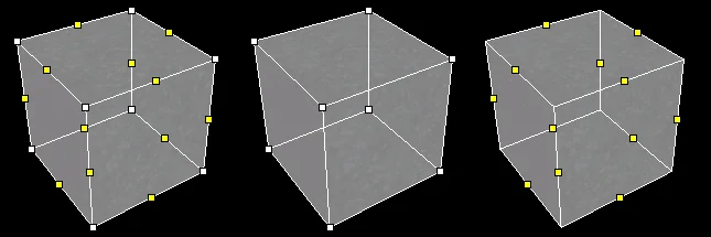
To enter the vertex mode, necessary:
  1. select object
  2. select the Vertex Manipulation tool [Shift-V]
To remove the mode of working with vertices you need to click on the red arrow (Selection Tool).
After switching to the vertex mode, the object becomes translucent. The object's vertices are replaced with white dots, and the edge centers are replaced with yellow dots.
Manipulation with vertices has 3 modes, which are switched in a circle by repeated clicks on the tool icon or the [Shift-V] key.
t4vertex10 In the first mode, you can move both the vertices and edges of an object;
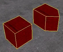
In the second - only the vertices;
In the third there are only ribs.

Simplest operations

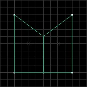
Now let's see how the simplest operations are performed. For example, what needs to be done to turn a cube into such an object (see the figure below on the right).
Transforming a cube
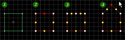
Sequence of actions (explanatory picture below):
  1. Building a cube
  2. Select it and select the Vertex tool, select the top point (the middle of the edge)
  3. Click Ctrl-Fto create an additional edge
  4. Select the center point again (white this time) and drag it up
t4vertex12 In 3-dimensional form Step 3 (creating a new edge between two points) looks like this:
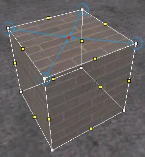
Adding an edge
To draw a new edge between two vertices in 3-D view, you must first select them (picture on the left) and then click Ctrl-F, a new edge will appear connecting the selected points (picture on the right).
In the top view (and any other 2-d view), unlike the 3-d view, when you click on a vertex, all "matching" vertices are selected, i.e. vertices located one behind the other. And when you drag such a point, the whole edge moves.
Creation of a pyramid
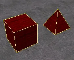
Let's practice working with vertices some more and turn the same cube into a pyramid (see figure below).
Turning a cube into a pyramid
Schematically, our actions look like this:
Move each of the 4 vertices to the center of the top side of the cube
We take turns moving each of the 4 vertices to the center of the top face of the cube. It is most convenient to first 3-d view, select one vertex and then, in 2-d view, move it to the center. This must be done with all four peaks.
When you move the second vertex (and then 3 and 4) to the center, a window like this will appear (see figure below) with a question "Merge vertices?", i.e. "Merge vertices?"
t3comperr8 Always answer "YES" to this question. It is difficult to imagine a case when you need to answer "NO"... Moreover, if you answer no, you will receive an error during compilation "Plane with no normal". Above we briefly described what its essence is, you can read a little more information about this error Here.
Scaling

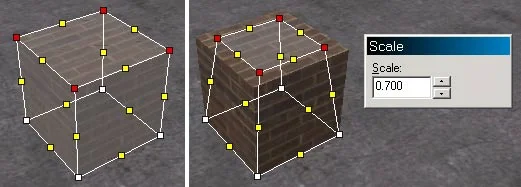
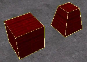
This operation is used quite rarely (if used at all ;-), but sometimes it can come in handy and significantly speed up the creation of, for example, a shape for light rays (Light Beam Effects). As a result, we will get something like a truncated pyramid (see figure below).
Transforming a cube into a truncated pyramid by scaling
  1. We build an object (in our case a cube)
  2. Select four vertices that form the top face
  3. Click Alt-E; a window appears with a choice of scale (picture on the right)
  4. Change the scale and click Enter
  5. For the changes to take effect, exit the vertex mode by clicking on Selection Tool
Select the top vertices and press Alt-E

Optimizing the map

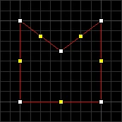
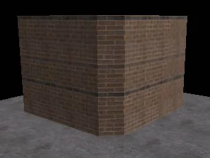
Vertex manipulation can be useful for map optimization. Let's look at this example: we want to create a wall with a truncated corner (see figure below).

Wall with truncated corner
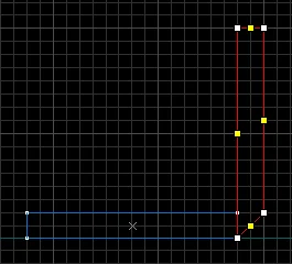
Instead of creating 2 separate brushes...
t4vertex19 ...it's better to create one large one with a truncated corner (see figure below).
t4vertex20 On any sufficiently large map you can find dozens of places where it is possible to use one large brush instead of 2-3 small ones - this technique allows you to reduce the overall map compilation time (since there are fewer brushes) and sometimes reduces r_speeds, which accordingly leads to an increase in fps.
Hence the rule :) - try, wherever possible, to use large (complex, as they are also called) brushes instead of several small ones.
This concludes our introductory article on working with object vertices. You can read more about using the vertex manipulation tool in the articles from the sections: "Arches", "Roofs" and "Advanced mapping" (creating mountains, tunnels and sewers).
5.7

My First Map

Well, well, this exciting moment has come when, with our help, you yourself will create your first map and be able to run around on it.
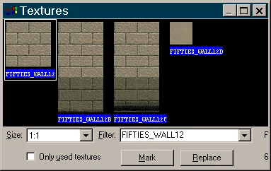
We hope that you have carefully read all the previous articles of the Tutorial, and therefore know how to create simple brushes, insert point entities, know how to texture objects and have an understanding of compilation (preferably with a BAT file). You will also need knowledge of the following entity objects: Launch the editor and create a new file [Ctrl-N]. Select the texture tool (colorful cube). On the panel that appears Face Properties click the button Browse. Down in the field Filter type the following: FIFTIES_WALL12 (we select the texture for the walls of the future room). If you have halflife.wad connected, then such a texture will be found, if not, connect halflife.wad (it is located in the valve directory with Half-Life). Select the very first texture.
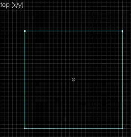
t6my1map1 Close the texture selection window. Set the top view (2D top), select the Block tool [Shift-B] and build a square with dimensions of 384x384 units (control the size in the status bar, below). Switch to 2D front view and lengthen the rectangle to 384 units as well. Finish creating the brush by pressing Enter.
t6my1map2 Select the brush you just created and click [Ctrl-H] . Now we will use the Hollow function discussed in the previous article. In the window that appears, leave the value 32 and click "OK".
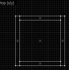
t4hollow3 Thus, we got a room with dimensions of 384x384x384 units and a wall thickness of 32 units (see figure below).
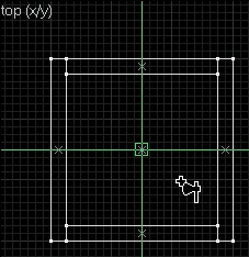
t6my1map3 Now you can look at the map in 3D textured form and fly inside the room. To move around in the 3D view, press Z once and use the W, A, S, D buttons and the mouse. As a result of all operations, your room in three-dimensional form should look something like this (see figure below):
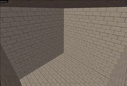
Room in 3D view
REMEMBER! No need to apply the Hollow function to every brush on the map! We did this to quickly create a room in which you can run around. Imagine that the brush is an ordinary construction board. So why turn every slab into a room, why turn every wall on the map into a room (we're not going to run around there anyway :), why turn the floor on map - This is absolutely not necessary! Here we just needed a room in which we could run, so we used the Hollow function. The exact same room can be obtained by creating 6 walls separately.
Now it's time to insert the 3 objects that we talked about at the beginning of the article. Let's insert the light source first, i.e. light object. Select the Entity Tool [Shift-E], then on the panel New Objects Select the light object from the list (see figure below).
t4ent4 Set the top view (2D top), move the cursor to the center of the room and click the left mouse button (see the figure below).
t6my1map5 Switch to 2D front view and place the light object under the ceiling (see figure below). Then press Enter to finish creating the light source.
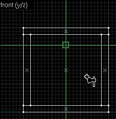
t6my1map6 So, we made a light bulb. Now it will be light on our map. Now all that remains is to create spawn points for counters and terrorists. As you already know, these points are the objects info_player_deathmatch (terrorist) and info_player_start (counter). One object - one birth point. In order for several players to play on the map, it is necessary to place several points for counters and terrorists.
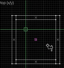
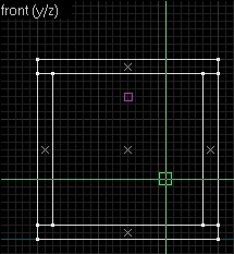
Just like in the case of the light bulb, select info_player_deathmatch from the list and set it as shown in the pictures below.
t6my1map7 t6my1map8 Please note that the info_player_deathmatch and info_player_start objects should not touch the walls (see the figure below, top view), each other and be raised some distance above the ground (see the figure below, front view). This must be done so that players do not die at the beginning of the round on their own and can move freely. Have you noticed on some maps, with high ping and lag, how players seem to fall to the ground at the beginning of the round? This happens precisely because there is some distance between the player and the ground. With a high-quality connection, such "landings" are almost unnoticeable.
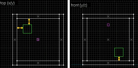
t6my1map9 So, we have already placed one terrorist birth point. Now create one contra spawn point in the same way. Select the info_player_start object from the list and insert it in a similar way, only in the opposite corner of the room (in the top view it will be the lower right corner).
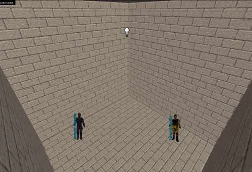
All! The first fully working map has been created! Of course, it still needs to be compiled, but for now compare what you got with our picture. If everything is approximately correct, save the map as my1map (or whatever) in RMF format and then in MAP format so that you can compile.
View of the finished map as 3D textured
To compile the map you need to create a BAT file. Copy the below lines into Notepad and save the file as COMPILE.BAT (the process of creating a BAT file is described in detail in the article How to Compile?).
Below we provide an example of a simple BAT file that you can use to compile your first map.
@echo off
set WADROOT=c:\games\half-life
set mapname=my1map.map
hlcsg.exe "%mapname%"
hlbsp.exe "%mapname%"
hlvis.exe "%mapname%"
hlrad.exe "%mapname%"
Place COMPILE.BAT to compilers, copy the map in *.MAP format there and run the BAT file. In a couple of seconds, the finished BSP card will be in the same directory.
Note: if the card name is not my1map, then change it in the line set mapname=my1map.map, and also change the path to the Half-Life directory if it is different.
And lastly, save your first card as a keepsake. Later, 5-6 months later, look at her. We are sure you will at least smile :)
my1map.zip [5Kb] - in the archive there is an example map in BSP and RMF formats.
5.8

Bomb Defusal Map (DE)

In this article we will tell you how to make a card with a bomb, i.e. DE card.
You will need to know just one new entity object in addition to the three already known (light, info_player_deathmatch, info_player_start): Bomb maps are the most popular among players. They combine dynamism and interesting gameplay. To create a good DE map, you need to understand the reason for the popularity of such maps as: de_dust, de_dust2, de_aztec, de_inferno. Look at how the bomb places are located on these maps, where the team bases are located, how the shelters are made, what the "relief" of these maps is (the maps are "multi-story") and, perhaps, you can do something similar :)
Let's move on to creating a DE map. On any DE map there should be 2 bomb sites (as it happens). These locations are determined by the object func_bomb_target.
Select the texture named AAATrigger using the method you already know. This is a special texture that is used for such objects. You may have several different looking AAATrigger textures. Which one should I use? I love it! It doesn't matter, in this case it's not the image of the texture that matters, but its name - AAATrigger.
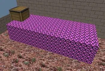
Now select the Block tool, select a suitable place on the map where the bomb will be planted and create a regular brush on it. The dimensions of the brush completely determine the area where the bomb can be planted (see figure below). For a terrorist to plant a bomb, he must only lightly touch this area.
Defining the bomb planting area using the func_bomb_target object
But a regular brush painted with the AAATrigger texture will not work. It needs to be turned into an entity. To do this, select it and click [Ctrl-T], in the window that appears, select an object from the list func_bomb_target. Close the window. The bomb site has been identified. Now the card will automatically be a DE card, i.e. at the start, one of the terrorists will be given a bomb.
Look at the picture above: a terrorist standing on the top box will not be able to plant a bomb, because it doesn't touch the object func_bomb_target. However, if this object is slightly increased in height, then it will be possible to plant a bomb, because the terrorist's feet will touch the object func_bomb_target.
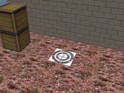
To somehow designate a place for planting a bomb (for the convenience of the players), you can apply a decal in the center, for example, as in the picture below (the name of such a decal is {TARGET and it is located in the file decals.wad). You can read about how to apply decals in the article How to Apply Textures and Decals?. You can also create your own texture with some kind of cross or letters A/B, indicating different bomb placement points. For example, this is done on de_dust/de_dust2, de_aztec (from CS 1.6).
Marking the bomb site with a decal
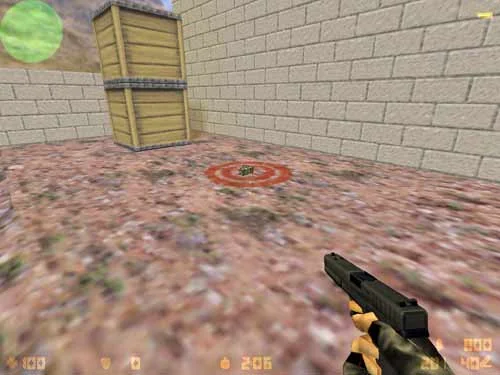
In the game the decal will look like this:
This is what the decal looks like in the game
As you can see, the object func_bomb_target in the game it is absolutely transparent, but its presence is indicated by a flashing bomb icon (on a terrorist with a bomb). Naturally, for a full-fledged map it is necessary to create several points of birth of players, the maximum number: 32, i.e. 16 each for terrorists and counters (no longer allowed by Half-Life). Choose the number of points depending on the size of the map. If the map is small, then perhaps 8 points on each side will be enough.
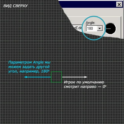
At objects info_player_deathmatch And info_player_start there are no special parameters other than the direction of the player's gaze after he is "born". The angle is set in the properties of these objects with a dash in a black circle or numbers (see the figure below). Properties are called up by pressing [Alt-Enter].
t6bomb7 As you can see from the picture above, by default at birth the player always faces to the right in the overhead view (0°). Imagine if the main passage is on the left, then the player will be forced to turn 180° at the beginning of each round, which is quite tiring and does not allow him to concentrate on buying weapons. In such cases, it would not be superfluous to indicate the angle of the viewing direction (as shown in the figure above).
Changing the radius of a bomb explosion

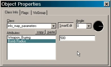
In some cases, for example when the map is very small, it can be useful to change the radius of the bomb explosion. This is done using a point entity object info_map_parameters. Insert one such object anywhere on the map (for convenience, you can near some bomb site). Such an object is inserted like any other point object, i.e. tool Entity Tool [Shift-E], select an object from the list info_map_parameters.
After installing the object, select it and click [Alt-Enter], properties will appear (see figure below).
t6bomb4 The first parameter "Weapon_Buying" indicates which team can buy weapons; by default, both teams can buy weapons (leave it unchanged).
But the second parameter is "Bomb Radius" - this is the radius of the bomb explosion. By default it is 500. For a small map, where there is practically no place to hide, you can set it to 350, and for a very large map you can set it more, for example, 650. In general, look at the size of your map and decide whether you need to change the radius of the bomb explosion. In most cases, mappers leave everything as is. In this case, you don't even need to create an object info_map_parameters - it's simply not needed.

Exact indication of the place where the weapon was purchased

The area where players can purchase weapons is automatically located right around their spawn points. However, it is possible to specify a precise (more extensive) area for purchasing weapons. To do this, create a brush filled with the AAATrigger texture, then it is transformed by pressing [Ctrl-T] to an entity object func_buyzone.
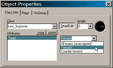
Object size func_buyzone and defines the area for purchasing weapons, beyond which you cannot buy weapons. Typically, this object is placed at team bases so that it covers all spawn points for players of one team. An important point after creating this area is to indicate which team can buy weapons within this area.
This is indicated in the properties of the object. Highlight func_buyzone and click [Alt-Enter]. The object properties will appear (see figure below).
t6bomb5 There is only one parameter "Team", its values ​​can be All teams (any of the teams), Terrorist (only terrorists), Counter-Terrorist (only counters). Naturally at the object func_buyzone on the base of counters you must select Counter-Terrorist, and for terrorists - Terrorist.
func_bomb_target.zip [14Kb] - in the archive there is an example map in BSP and RMF formats.
5.9

Hostage Rescue Map (CS)

In this article we will tell you how to make a map with hostages, i.e. CS card.
You will need to know two new entity objects: To turn a map without a type into a CS map, you need to place hostages and determine the place of their rescue (where the counters will take them).
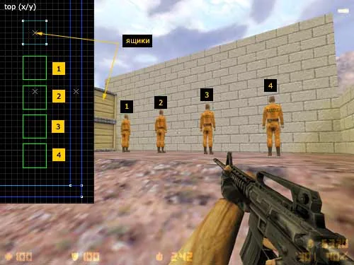
First, let's determine the places of "birth" of the hostages. They are created by a point entity object hostage_entity (1 object - 1 hostage). These objects are installed in exactly the same way as the usual points of "birth" of players (info_player_deathmatch and info_player_start), the same rules apply: the object should not touch walls and other similar objects, and it should also be located slightly above (8-16 units) the ground.
The figure below in the top view (2D top) shows how hostages are installed in the editor, and how it looks in the game.
Arrangement of hostage_rescue objects (hostages)
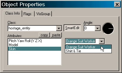
Hostages (hostage_entity object) have some properties that are called by [Alt-Enter] (see picture below).
t6hostage3 The first "Pitch Yaw Roll" is nothing more than the direction of the hostage's "gaze". It is easier to display it in a black circle, focusing on the top view (2D top).
The second "Model" is the model of the hostage. If you have some other hostage model, then you can specify the path to it in this parameter (usually it should be copied to the cstrike/models.. folder). But remember that in this case this model will have to be distributed along with the map, because other people do not have such a model.
And the last "Skin" is the choice of skin (clothes) for the hostage. If the model has several skins, then here you can choose what the hostage will wear. The standard model has 2 skins to choose from: yellow overalls (as in the picture) and a light shirt, dark pants.
Now let's define the area for hostage rescue. Select the texture named AAATrigger using the method you already know. This is a special texture that is used for such objects. You may have several different looking AAATrigger textures. Which one should I use? I love it! It doesn't matter, in this case it's not the image of the texture that matters, but its name AAATrigger.
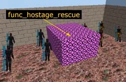
Now select the Block tool, determine the place on the map where the hostages must be brought to be rescued and create a regular brush on it. The dimensions of the brush completely determine the area where hostages can be brought (see figure below).
Defining a hostage rescue area using the func_hostage_rescue object
But a regular brush painted with the AAATrigger texture will not work. It needs to be turned into an entity. To do this, select it and click [Ctrl-T], in the window that appears, select an object from the list func_hostage_rescue. Close the window. The hostage rescue area has been identified. Now the card will automatically be a CS card.
Naturally, for a complete map it is necessary to place several birth points of players, the maximum number: 32, i.e. 16 each for terrorists and counters (no longer allowed by Half-Life). Choose the number of points depending on the size of the map. If the map is small, then perhaps 8 points on each side will be enough.
At objects info_player_deathmatch And info_player_start there are no special parameters other than the direction of the player's gaze after he is "born". The angle is set in the properties of these objects with a dash in a black circle or numbers (see the figure below). Properties are called up by pressing [Alt-Enter].
t6bomb7 As you can see from the picture above, by default at birth the player always faces to the right in the overhead view (0°). Imagine if the main passage is on the left, then the player will be forced to turn 180° at the beginning of each round, which is quite tiring and does not allow him to concentrate on buying weapons. In such cases, it would not be superfluous to indicate the angle of the viewing direction (as shown in the figure above).
In the very first picture, all the hostages are turned backwards towards us :). This happened because the angle (the "Angle" parameter) is 0° by default. In order for the hostages (on this particular map) to face us, it is necessary to set the angle to 180° in the properties. You may not need to change this angle on your map, it all depends on the location of the walls on the map.

Exact indication of the place where the weapon was purchased

The area where players can purchase weapons is automatically located right around their spawn points. However, it is possible to specify a precise (more extensive) area for purchasing weapons. To do this, similar to func_hostage_rescue, a brush is created, filled with the AAATrigger texture, then it is transformed by pressing [Ctrl-T] to an entity object func_buyzone.
Object size func_buyzone and defines the area for purchasing weapons, beyond which you cannot buy weapons. Typically, this object is placed at team bases so that it covers all spawn points for players of one team. An important point after creating this area is to indicate which team can buy weapons within this area.
This is indicated in the properties of the object. Highlight func_buyzone and press [Alt-Enter]. The object properties will appear (see figure below).
t6bomb5 There is only one parameter "Team", its values ​​can be All teams (any of the teams), Terrorist (only terrorists), Counter-Terrorist (only counters). Naturally at the object func_buyzone on the base of counters you must select Counter-Terrorist, and for terrorists - Terrorist.
func_hostage_rescue.zip [14Kb] - in the archive there is an example map in BSP and RMF formats.
5.10

VIP Assassination Map (AS)

In this article we will tell you how to make a card with a VIP, i.e. as-card.
You will need to know two new entity objects: AS maps are not as popular as DE or CS, but since they are standard modes in CS, we will describe how to create them. Let us remember that the AS card is a map with a VIP (a player with a pistol who cannot buy weapons), counters must take him to a certain place on the map (often there are two of these places), and terrorists must prevent him from doing this. A typical example of an AS map is as_oilrig. Look at the principles on which it is made, where the counters appear and where the terrorists are, where the points for rescuing the VIP are located, what shelters are on the side of the terrorists, etc.
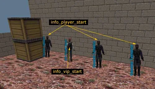
Let's start creating an AS map. First, we will determine the location where the VIP will appear (we will create an object info_vip_start). Naturally, there should be only one VIP, therefore the object info_vip_start only one should be created. The object is installed in the same way as the usual points of "birth" of players (info_player_deathmatch and info_player_start), the same rules apply: the object should not touch walls and nearby info_player_start objects, and it should also be slightly higher (8-16 units) of the ground. VIP should be installed next to the rest of the counters. If you make 10 terrorist spawn points, then there should be 9 + 1 VIP counters.
Determining the location of the VIP's appearance using the info_vip_start object
Now let's determine the place to which the VIP's counters should be taken. This is done using the object func_vip_safetyzone. Select the texture named AAATrigger using the method you already know. This is a special texture that is used for such objects. You may have several different looking AAATrigger textures. Which one should I use? I love it! It doesn't matter, in this case it's not the image of the texture that matters, but its name AAATrigger.
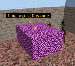
Now select the Block tool, determine the place on the map where the counters should lead the VIP, and create a regular brush on it. The dimensions of the brush completely determine the area where the VIP needs to be brought (see figure below).
Defining the VIP rescue area using the func_vip_safetyzone object
But a regular brush painted with the AAATrigger texture will not work. It needs to be turned into an entity. To do this, select it and click [Ctrl-T], in the window that appears, select an object from the list func_vip_safetyzone. Close the window. The VIP's rescue area has been determined. The card will now automatically be an AS card.
Naturally, for a complete map it is necessary to place several birth points of players, the maximum number: 32, i.e. 16 each for terrorists and counters (no longer allowed by Half-Life). Choose the number of points depending on the size of the map. If the map is small, then perhaps 8 points on each side will be enough.
At the object info_vip_start there are no special parameters, except for the direction of the VIP player's gaze after he is "born". The angle is set in the properties of the info_vip_start object with a dash in a black circle or numbers (see the figure below). Properties are called up by pressing [Alt-Enter].
t6bomb7 As you can see from the picture above, by default at birth the player always faces to the right in the overhead view (0°). Imagine if the main passage is on the left, then the player will be forced to turn 180° at the beginning of each round, which is quite tiring and does not allow him to concentrate on buying weapons. In such cases, it would not be superfluous to indicate the angle of the viewing direction (as shown in the figure above).

Exact indication of the place where the weapon was purchased

The area where players can purchase weapons is automatically located right around their spawn points. However, it is possible to specify a precise (more extensive) area for purchasing weapons. To do this, create a brush filled with the AAATrigger texture, then it is transformed by pressing [Ctrl-T] to an entity object func_buyzone.
Object size func_buyzone and defines the area for purchasing weapons, beyond which you cannot buy weapons. Typically, this object is placed at team bases so that it covers all spawn points for players of one team. An important point after creating this area is to indicate which team can buy weapons within this area.
This is indicated in the properties of the object. Highlight func_buyzone and press [Alt-Enter]. The object properties will appear (see figure below).
t6bomb5 There is only one parameter "Team", its values ​​can be All teams (any of the teams), Terrorist (only terrorists), Counter-Terrorist (only counters). Naturally at the object func_buyzone on the base of counters you must select Counter-Terrorist, and for terrorists - Terrorist.
func_vip_safetyzone.zip [14Kb] - in the archive there is an example map in BSP and RMF formats.
5.11

Escape Map (ES)

In this article we will tell you how to make a map where terrorists need to escape, i.e. ES card.
You will need to know three new entity objects: ES maps are probably the most unpopular of all card types. There is not a single ES map in the official set of CS maps (maybe you will create an ES map that will be included in CS? :). However, let's take a look at how they are created. Let us remind you that ES maps are a type of maps on which terrorists must reach a certain place in an amount of 50% or more, then they win. Weapons can be purchased on ES maps only contras, and terrorists must find it in some place (purchase for terrorists is prohibited).
A typical example of an ES card is es_cell. See where the players spawn, where the terrorists' weapons are laid out, and where they should run.
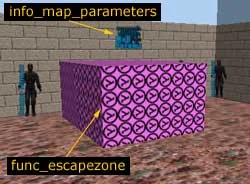
Let's start creating the ES map. First, we determine the place to which the terrorists must run in order to be considered escaped. To do this, select the Block tool and create a brush in the right place, colored on all sides with the AAATrigger texture. Then select it and transform it by pressing [Ctrl-T] in entity. Select an object from the list func_escapezone. The size of the object completely determines the area where the terrorists must run (see figure below).
Determining the place where terrorists should run using the func_escapezone object
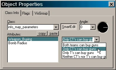
Now, according to the rules of ES maps, it is necessary to prohibit terrorists from buying weapons. This is done using a point entity object info_map_parameters. Select a tool Entity Tool [Shift-E], then select the object in the list info_map_parameters and paste it somewhere inside the card (where exactly doesn't matter).
Select this object and click [Alt-Enter], its properties will appear in front of you. In the "Weapon_Buying" parameter you must select "Only CT's can buy guns" (see figure below). Now only opponents will be able to buy weapons.
t6escape2 Now somewhere closer to the terrorists you need to place weapons, grenades and body armor. This is done by a point object armoury_entity . One such object inserts one weapon, one grenade, or one body armor onto the map. But in the properties of this object you can specify their number, for example, five AK-47 or 4 HE grenades.
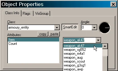
Select a tool Entity Tool [Shift-E], then select the object in the list armoury_entity and insert it in some place closer to the terrorists' base (since this weapon is intended for them). Select this object and click [Alt-Enter]. Its properties will appear (see figure below).
t6escape3 The "Item" parameter indicates the type of weapon, type of grenade or body armor. In the "Count" parameter - the amount of selected equipment.
Naturally, for a complete map it is necessary to place several birth points of players, the maximum number: 32, i.e. 16 each for terrorists and counters (no longer allowed by Half-Life). Choose the number of points depending on the size of the map. If the map is small, then perhaps 8 points on each side will be enough.
At objects info_player_start And info_player_deathmatch there are no special parameters other than the direction of the player's gaze after he is "born". The angle is set in the properties of these objects with a dash in a black circle or numbers (see the figure below). Properties are called up by pressing [Alt-Enter].
t6bomb7 As you can see from the picture above, by default at birth the player always faces to the right in the overhead view (0°). Imagine if the main passage is on the left, then the player will be forced to turn 180° at the beginning of each round, which is quite tiring and does not allow him to concentrate on buying weapons. In such cases, it would not be superfluous to indicate the angle of the viewing direction (as shown in the figure above).

Exact indication of the place where the weapon was purchased

The area where players can purchase weapons is automatically located right around their spawn points. However, it is possible to specify a precise (more extensive) area for purchasing weapons. To do this, create a brush filled with the AAATrigger texture, then it is transformed by pressing [Ctrl-T] to an entity object func_buyzone.
Object size func_buyzone and defines the area for purchasing weapons, beyond which you cannot buy weapons. Typically, this object is placed at team bases so that it covers all spawn points for players of one team. An important point after creating this area is to indicate which team can buy weapons within this area.
This is indicated in the properties of the object. Highlight func_buyzone and press [Alt-Enter]. The object properties will appear (see figure below).
t6bomb5 There is only one parameter "Team", its values ​​can be All teams (any of the teams), Terrorist (only terrorists), Counter-Terrorist (only counters). Naturally at the object func_buyzone on the base of counters you must select Counter-Terrorist, and for terrorists - Terrorist.
func_escapezone.zip [14Kb] - in the archive there is an example map in BSP and RMF formats.
5.12

Other Map Types

In this article we will look at creating such types of maps as: DM, FY, KA, PA.

1. DM — Deathmatch

Regular desmatch or myasilovo. No bombs, hostages or other hassles. Some mappers also scatter weapons across team bases so as not to waste time purchasing them.
Distinctive features of DM maps are:
  1. Simplicity of design
  2. Fast gameplay
  3. Maximum Myasilov
If you make a DM map, make it simple so that players can fully learn it in 2-3 rounds. You shouldn't make a box map when the teams see each other already at the start. There still needs to be some kind of planning.
If you decide to place a weapon on the map (for example, place an AK on the base of the terras and an M4 on the counters), then use the object for this armoury_entity.
Well, one last thing. If you want to see a real representative of this genre of maps, then download dm_aztec_maso2 (1.3 MB) or dm_aztec_maso3 (1.2 MB). Hours of exciting gameplay are guaranteed :)

2. FY - same eggs only in profile

Everyone knows the map fy_iceworld, whose popularity around the world is enormous.
For those who don't know what fy_iceworld and its numerous clones are: it's a super small map, four boxes (rocks) around which players run + weapons of all kinds at team respawns. The map is completely symmetrical, which perhaps distinguishes this type of map from DM.
Not many FY maps are made, to say the least. It's just that some mappers, jealous of the popularity of iceworld, are trying to reinvent the wheel and make their own unique fy-map. The result is a CLONE.
In general, if your map is completely symmetrical and there are weapons of all types scattered around the bases, then it might make sense to call it FY.

3. KA - Knife Arena (on knives)

Myasilovo on knives. From time to time, players switch to knives when they get tired of guns. All standard maps are not very suitable for knife play (they are too large). In such situations, special Knife Arena maps help.
On such maps, the purchase of weapons is prohibited, pistols are confiscated, knives are issued, and nothing else. True, some KA maps have grenades and body armor. Based on the name (Arena), maps of this genre represent a kind of open space (essentially a large open or closed box), but there are exceptions.
Here is a list of entity objects used when creating a ka map:
  • player_weaponstrip - selects weapons
  • game_player_equip - supplies players with weapons (knives in our case)
  • info_map_parameters - prohibits purchase
Want to see a very unusual KA card? Then search and download KA_100x100, you've probably never seen anything like it before :-)

4. PA - Prepared Assault, as well as Pistol Arena

This type of card is rare. Regarding Prepared Assault, then this mode is not much different from DM.
Pistol Arena - it's something like Knife Arena, but only with pistols. The entities used are exactly the same, only pistols are issued instead of knives.
In addition to Pistol Arena and Knife Arena, AWP arenas are also common, and so on. The only difference between these modes lies in the weapons given to players. Essentially it's all good old Deathmatch.