Chapter VIII. Lighting.

Lighting guide: natural and artificial light sources, light rays, glow and haze effects, rotating beacons, and fire.

8.1

Overview of Map Lighting

In this article we will briefly introduce you to all the possible ways of illuminating a map, which, by the way, are not many, and we will also briefly talk about each of them.

Two main types of lighting

Lighting in Half-Life, as in real life, is divided into 2 main types:
  1. Natural (sunlight)
  2. Artificial (light bulb)
Each of these two types of lighting is implemented using different entities.

1. Natural light (sun)

Whatever card you take, it has natural light. It is implemented using a point entity object light_environment And SKY brushes, surrounding the card outside and separating it from the "vacuum" outside it.
Object light_environment sometimes they jokingly call maps "suns", for example they say: "Insert a sun and everything will be fine" :) Remember that for a map one such sun is enough, there is no point in creating several objects light_environment no (it used to be :)
As for the second prerequisite for natural lighting to work, namely SKY brushes, then they are simple brushes, only painted on all sides with a special SKY texture (blue). This texture has the ability to emit light (if there is a light_environment object on the map). Sometimes the entire set of SKY brushes, forming a kind of dome over the map, is simply called "the sky" and they say: "create a sky," meaning to create SKY brushes around the map.
In object properties light_environment The color of the light and its brightness are set. The appearance of the map after compilation greatly depends on these parameters. Typically, mappers choose colors close to yellow, orange, brown or white - in general, closer to natural, daylight. The properties of this object also indicate the angle at which the light hits the ground. The default is -90°. "Minus" indicates that the light is tilted towards the ground. Remember that you should only enter negative values ​​(-30°, 45°, -60° and others). The size of shadows cast by objects depends on this angle. Indeed, the length of the shadow changes when the angle of incidence of light changes (as the Sun moves). For example, to create a morning map when the Sun is not high above the horizon, you need to specify values ​​close to -30°, etc.

2. Artificial lighting (light bulbs)

In principle, it is possible to imagine a map without artificial lighting if there are no shelters, rooms, basements, caves, etc. on it. Most maps have cover, which means there is artificial lighting.
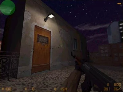
Artificial lighting can be created using point entities light And light_spot or luminous textures. The first object illuminates the room like a regular light bulb, the second creates directional light (like a spotlight). Light_spot used much less frequently than light and mainly for decorative lighting (billboards, paintings), and can also be used to create street lamps.
Artificial lighting can also be created using luminous textures. This method has also found its application. You can read more about glowing textures in the article "Glowing textures (creating a RAD file)."
8.2

Natural Lighting (light_environment)

In this article we will talk about creating natural (basic) map lighting (from the sun). Before reading the article, familiarize yourself with the properties of the following entity object: General (natural) lighting in Half-Life is created using an object light_environment. It is necessary to place ONE such object on the map and set the necessary properties.
Usually light_environment placed slightly above the main walls of the map, as if in the place of the sun. To illuminate the map, it is enough to place ONE such object.
Let's look at the properties of this object:
Pitch Yaw Roll (Y Z X)
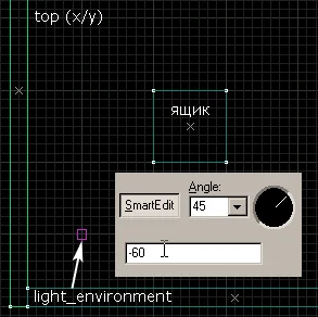
Light direction in three coordinates. But it is much more convenient to use a compass (circle) called "Angle" + the "Pitch" parameter to determine the angle of the rays to the ground (see figure below). When determining the direction of light using "Angle", always set the view from above (2D top).
t7lightenv2 Let's say we want the shadow of the box and the walls (and all other objects on the map) to be cast up and to the right (in the picture). Then in properties light_environment you must specify an angle of 45 degrees or any other pointing up and to the right. Remember that the angles must be set in the top view, otherwise the direction will be set incorrectly.
Pitch
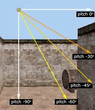
The angle, in degrees, at which light strikes the ground. Use only negative values ​​here (-30°, -45°, 60° and others). "Minus" means the light is directed toward the ground. For example, a value of -90° means that the light is falling perpendicularly downwards. Commonly used values ​​are -60°, -45° and -30°.
The picture below is a little crooked :), but still shows the main angles used (pitch) for the object light_environment:
Basic angles used (pitch) for the light_environment object
Brightness X X X X
The color (in RGB format - red, green, blue) and light brightness (0-255) are indicated here. The first three numbers determine the color of the light. You can select it by clicking on the "Pick color" button. Typically, mappers choose colors close to yellow, orange, brown or white - in general, closer to natural, daylight. The last number determines the brightness of the light from 0 to 255. Typically, a brightness of 150 is enough to create a fairly light map. Practice with different brightness and color values; they greatly affect the appearance of the map. Proper lighting can work wonders - this is an irrefutable fact!
For dark maps (evening, twilight), set small brightness values ​​from 10-15 and select a corresponding dark sky picture. Agree, the light sky from de_dust will look rather ridiculous on a dark map.
Also, when choosing a color, take into account the main color of your map (the color of the prevailing textures). So for example, if the map has a lot of gray (like de_aztec), then the map will look best illuminated with white light or light with shades of gray, if the map is yellow, like de_dust, then light with shades of yellow or orange will work well, etc.

Minimum map illumination

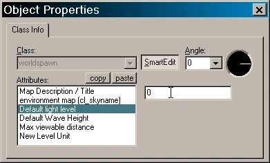
It is possible to specify the minimum illumination on the map. This is done in the menu Map/Map properties... (see picture below).
t7lightenv3 Map Description / Title
(does not apply to lighting) Here you can enter the name of the card and who made it, for example: De_Lalala by Somebody!
Environment map (cl_skyname)
(does not apply to lighting) The name of the picture used as the sky is indicated here. You can read more about this in articles devoted to creating the sky.
Default light level
But this is exactly what we need - the minimum level of map illumination. Most mappers leave the value zero here, but some like to set "something", for example, 75. In the latter case, any unlit room will be illuminated with a brightness of 75 units. It should be noted that setting a number greater than zero in this parameter does not eliminate the need to place at least one light source on the map. This is a must! Otherwise, without light sources, an error will occur at compile time.
Max viewable distance
(does not apply to lighting) Maximum visible distance on the map. If you suddenly notice that in certain places (usually this happens in large open spaces) distant objects are not drawn (walls disappear, etc.), then you need to increase this parameter. The default value here is 4096 units. The maximum value is 2 times higher: 8192. There is no point in setting an EVEN higher value, objects will still be hidden.
The remaining parameters must be left as is.

Possible problems with light_environment

It seems to us that there can only be one problem: if after compilation your map is completely dark, then this means that the object light_environment is located inside some kind of brush (in a wall, rock, etc.).
So we figured out the natural lighting on the map.
8.3

Artificial Lighting (light & light_spot)

In this article we will talk about creating artificial lighting (from light bulbs). Before reading the article, familiarize yourself with the following entity objects: Objects light And light_spot used to illuminate rooms (rooms, basements, etc.), where external light from the object light_environment does not hit or is not enough.
Let us first consider the most commonly used in practice and simpler object light.

1. Light object

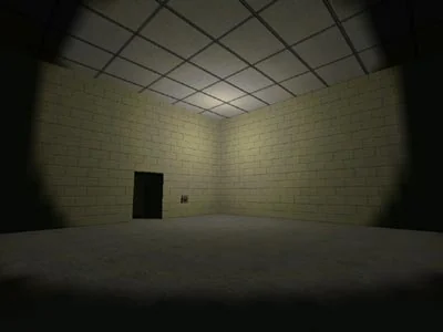
Object light In fact, it is the most ordinary light bulb. The light from it spreads in all directions, as if creating a sphere. This is what lighting a dark room with such an object looks like:
This is what the lighting from the light object looks like
Let's consider the properties of the object light.
Name
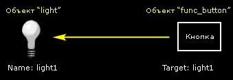
Name of the object (light bulb). The name should be specified if the light bulb is supposed to be turned on/off using a button or some other object. Below is a diagram where pressing a button (func_button) will turn off the light (light) named light1. Pressing again will turn on the light.
t7light4 Target
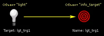
When creating a simple light bulb, this parameter is left empty. If you want light to travel in a specific direction, then a point object is created at the location where the light should be directed info_target or its complete analogue info_null. Then this object is given a name and entered into the properties of the light bulb, in the "Target" parameter. In this case, the light bulb will shine in the direction of this object (the object is completely invisible in the game). The figure below shows the diagram.
t7light1 Appearance
Rarely used option. It indicates the type of light bulb (flashing, flickering, etc.). To create a simple light bulb that shines constantly, you don't need to specify anything.
Custom Appearance
Another less useful parameter. Using it you can set the flickering pattern of the light bulb. To do this, combinations of letters of the English alphabet are used from a to z, Where a - an extinguished light bulb, z - burning. For example, the combination abcdedcba will cause the light bulb to light up first, then go out, then repeat. To be able to set your own flickering mode, you need to give the light bulb a name. To create a regular light bulb, you don't need to write anything here.
The light does not light up at the start of the round
If it is necessary that the light is not lit at the beginning of the round, then in the tab Flags It should be noted "Initially dark". To turn it on you will need a button or some kind of trigger.
Brightness
The main parameter that determines the color and brightness of the light emitted by a light bulb. Color is indicated in RGB format - red, green, blue, and brightness with values ​​from 0 to 255. The first three digits determine the color of the light. You can select it by clicking on the "Pick color" button. The last digit determines the brightness of the light from 0 to 255. Typically brightness values ​​from 100 to 200 are used.

2. Light_spot object

Now let's look at the second object − light_spot. It is used to create a directional light, and in doing so we can control the "width" of the beam. This object has slightly more properties than light. In addition to the same parameters as Name, Target, Brightness, Appearance and Custom Appearance, this object has the following:
Inner (bright) angle
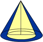
Angle of the inner cone (imagine a cone along the axis of light propagation, the angle of this cone is this parameter). The brightness of the light inside this angle (cone) will be maximum. The default value is 30 degrees.
Outer (fading) angle
The angle of the outer cone that forms the shading (diminishment) of light. The default value is 45 degrees.
In the figure below, the "Inner angle" is shown as a yellow cone, and the "Outer angle" is shown as a blue cone.
t7light5 See how the lighting changes depending on these angles. On the left are the default angles, on the right are 90° and 105°.
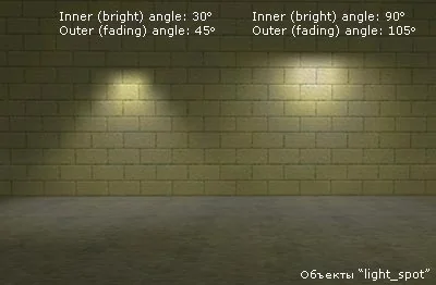
Change in lighting by light_spot object depending on angles
Pitch
The head under which the rays fall to the ground. A negative value means the rays are directed downwards, a positive value means the rays are directed upwards. In general, we recommend always using the object info_target or info_null (any of them) to indicate the direction of incidence of light. It's easier, clearer and faster than setting angles manually. In addition, you will know exactly where the light will be directed.
Is Sky
There are two options here: No and Yes. Default is No. The value "Yes" is used to create the effect of lighting from the sky, without the light coming from the light_spot itself. Usually the default value is left - "No".
8.4

Light Ray Effect

In this article we will talk about creating one beautiful effect that will help decorate your card. We are talking about visualizing rays from light sources. To make such rays, you must be able to work with vertices (vertices of objects). Before reading the article, familiarize yourself with the following entity object: The picture below clearly shows what kind of effect we are talking about:
This is what the rays look like in the game
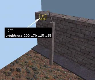
This effect looks best in a dark place, which is why our example map does just that. First, let's create a small flashlight from several brushes (black in the picture) and place a light bulb under it, i.e. object light, which we wrote about in the previous article. You can also use the object light_spot (for it you will need to indicate the direction of light with the object info_target).
This is what we got (see figure below).
Create a light object under the lantern
At the object light Let's set the properties. Which? Choose for yourself, now you know how to do it :)
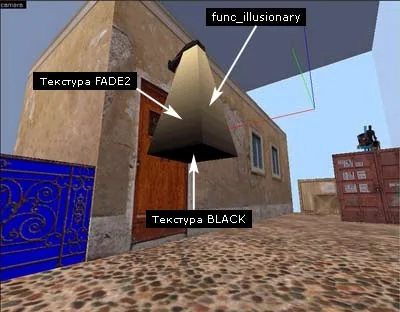
Now select a texture FADE2 (yellow-black gradient texture), it is in the standard largest texture library halflife.wad. This texture, with certain properties of the object, will be transparent on the black side and translucent on the yellow side. By the way, you can create a similar texture, and in any color. For example, on the map KA_100x100 I used blue, green and pink textures to create the corresponding color rays.
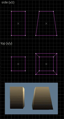
Create a regular brush under the lantern and use the vertex tool to expand the lower surface of the brush. This brush will determine the shape of the outgoing rays. The picture below shows the original brush and the modified brush with the shape of a truncated pyramid.
t7lightbeam4 Place this brush under the lantern (see picture below).
Move the vertices on the bottom edge of the brush apart
Align the textures so that the light (yellow) part is on top and the dark (black) part is on the bottom (see picture above). Paint the bottom edge of the brush with texture BLACK, this line will be transparent in the game.
Now select the brush and transform it [Ctrl-T] to object func_illusionary. We use this object because... we need to be able to walk through the beams, and not stumble over them. Now let's set the following properties:
Render Mode: Additive
FX Amount: 20 (the higher the value, the more visible the rays are)
That's all. The effect is beautiful and often used, now you know how to do it.
light.zip [16Kb] - in the archive there is an example map in BSP and RMF formats.
8.5

Light Haze / Glow Effect (env_glow)

In this article we'll look at creating another interesting effect around lights that will help give them a more realistic look. We are talking about creating haze (glow, halo). Before reading the article, familiarize yourself with the following entity object: You could see a similar effect on the map cs_italy, there are small wall lanterns around which rays spread (haze, halo). Now we will do something similar. Suppose we have a lantern on the map with a regular light source light (see picture below).
Create a light object under the lantern
To create haze, sprites are used, i.e. files with extension *.spr. These files are located in the directory cstrike/sprites.. We will use a sprite named flare1.spr. If you do not have such a sprite, then you can take it from the pak0.pak archive, which is located in the valve folder.
So to insert a sprite we use a point entity env_glow. We place it under the lantern, quite close to the surface of the lantern. In the editor object env_glow displayed as a fairly large square, much larger than, for example, the light source light (see picture below).
t7lightglow2 We'll put it up for env_glow the following properties:
Render FX — Normal (you can also use Constant Glow, explained in more detail below)
Render Mode - Glow (env_glow should always have this mode)
FX Amount — 150 (the higher the value, the brighter the haze. Maximum: 255)
FX Color — 255 255 200 (the color of the haze, in this case pale yellow, in principle can not be set)
Model - sprites/flare1.spr (you can also use other sprites named flare or glow)
Now more about the parameter Render FX. For sprites it is recommended to set 2 modes: Normal or Constant Glow.
The only difference between these modes lies in the different intensity (brightness, saturation) haze when the player approaches/moves away from the sprite.
In mode Normal As the player moves away from the sprite, its brightness decreases and the sprite becomes less visible. At Constant Glow The sprite always has a constant brightness, regardless of the player's viewing distance. Try both options, sometimes Normal looks better, sometimes Constant Glow.
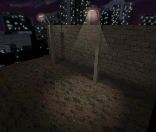
That's all! We compile, run and see the following effect:
This is what the haze effect looks like in the game
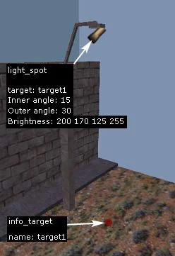
In our example map, we created another lantern (in the picture on the right). It is slightly different from the one on the left. Around it we created all the effects discussed in previous articles: we created rays from func_illusionary, haze from env_glow and instead of a simple light, a directional light was used light_spot (see picture below).
Create a light_spot and info_target object
Object properties light_spot and targets info_target, used to set the direction of light, are shown in the figure.
env_glow.zip [19Kb] - in the archive there is an example map in BSP and RMF formats.
8.6

Rotating Light (Beacon / Disco Effect)

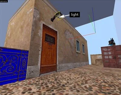
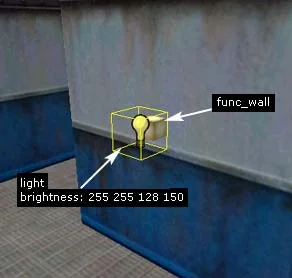
In this article we will talk about creating a rotating light (like a strobe light). To implement this effect, you will need the ability to work with vertices, as well as knowledge of the following entity object: First, let's create a small brush that will represent a light bulb. Let's transform it [Ctrl-T] to object func_wall, so that it does not break the wall it comes into contact with into additional polygons. There is no need to set any properties for func_wall.
Now in front of the light bulb we will place a light source, an ordinary one light (see picture below).
Create a light object under the light bulb
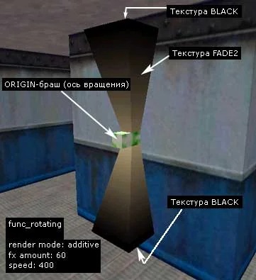
And now you will need skills in working with vertexes. We begin to create the shape of the rotating rays. We use a standard gradient texture FADE2 or FADE, as we did in the article about creating light rays. An important point is the correct application of texture to future rays. Dark (black) places should be at the edges of the rays, and light (yellow) in the middle. You may have to change the scale of the texture, rotate it, apply different alignment. It should look something like this:
We create rays from two brushes (FADE2 texture) and a rotation axis brush (ORIGIN texture)
The small white and green brush is an ORIGIN brush (a regular brush painted on all sides with a special ORIGIN texture). It is necessary for any rotating object, because... indicates the axis of rotation (the Tutorial has a very detailed article on the correct use of ORIGIN brushes). Since we have a rotating light, we need to create such a brush.
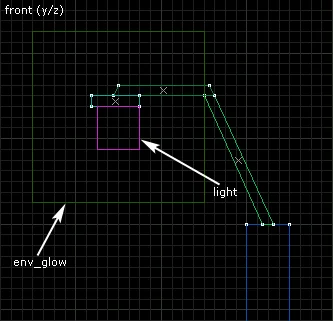
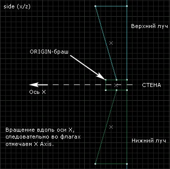
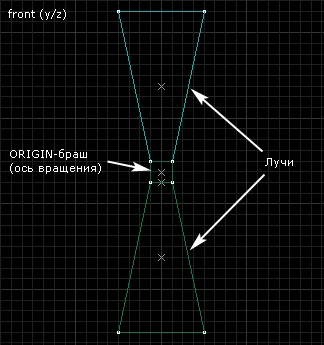
The placement of the ORIGIN brush is very important. Since our rays will rotate along the wall, the ORIGIN brush should be placed between the two rays (exactly in the middle). For clarity, we have lengthened the ORIGIN brush along the axis along which the rotation will occur. The pictures below show the side and front views.
t7lgtrotate5 t7lgtrotate4 Next important point. We transform the prepared two brushes (rays) and the ORIGIN brush into a single entity object func_rotating. To do this, select while holding down the key Ctrl both rays and ORIGIN brush. Click [Ctrl-T] and select from the list func_rotating.
Now let's set the properties func_rotating:
Render Mode — Additive (so that the rays are transparent);
FX Amount — 60 (transparency of the rays, the higher the value, the more clearly the rays are visible. Maximum: 255);
Speed — 400 (ray rotation speed, you can experiment);
Let's leave the rest of the parameters as they are for now.
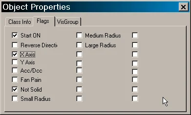
In addition to the properties, you should definitely set some flags (see figure below).
t7lgtrotate3 Start ON — so that the rays begin to rotate automatically after the start of the round;
Not Solid — is necessary so that the player can freely pass through the rays. Otherwise he will hit his head on them :)
X Axis — here the axis of rotation of the rays is determined. Possible values: X Axis or Y Axis, which define rotation around the corresponding axes. If you leave these flags unchecked, the rays will rotate around the vertical Z axis, which in any view is directed from bottom to top.

Defining the axis of rotation

Let's take a closer look at this very important point in determining the axis of rotation.
ORIGIN brush included in the object func_rotating its center defines the point in space around which rotation occurs. And the actual rotation axis is selected in the flags: either X or Y. Let us recall that if the flags are not checked, the rotation will occur around the vertical Z axis (see two pictures above).
The rays are ready. We compile, run and see the following result:
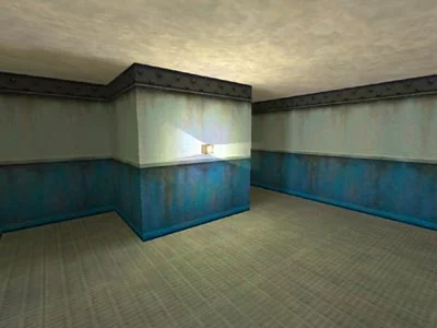
This is what the rotating rays look like in the game
If it is necessary for the rays to rotate in the opposite direction, then check the box Reverse Direction.
rotating_light.zip [9Kb] - in the archive there is an example map in BSP and RMF formats.
8.7

Light Blocking by Entities

In this article we will talk about how you can control the shadows of entity objects.
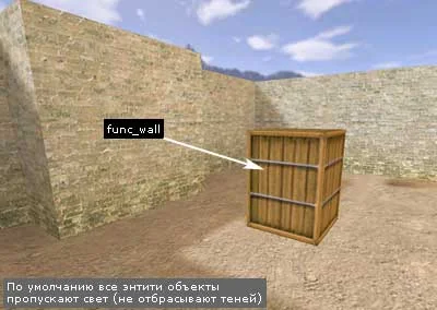
All brush entities allow light to pass through by default, i.e. do not cast shadows. Agree, a box that does not cast a shadow looks rather ridiculous, while the walls located nearby do cast one (see the figure below).
Entity objects do not cast shadows
Of course, instead of a box from func_wall it was possible to use a regular brush, which would naturally "cast" a shadow, but then the ground would be broken up into smaller polygons. If there are not many boxes, then you can use regular brushes, but if there are 10 of them in one place, then they can seriously reduce the speed of map drawing (lower fps).
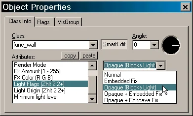
In order for an entity object to cast light, it must be set to light flags. Most brush entities have these flags, and they are available in the object properties (see figure below). But remember that light flags available only when using compilers ZHLT or ZHLT: Custom Build. The flags do not work with standard (old) compilers. t7shaddow4

Possible options

  • 1. Normal — default (the object does not cast shadows);
    2. EmbeddedFix - do not use complex lighting correction. Sometimes a brush object passing through a wall is not properly lit. Use this flag to avoid this situation;
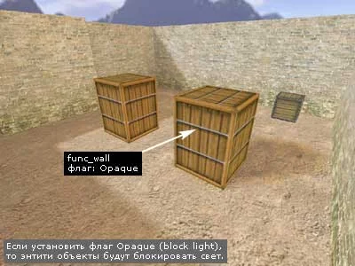
    3. Opaque (Block Light) — the object casts shadows. Makes an object "opaque", causing it to cast a shadow. It is useful to use this flag on func_wall, some func_illusionary, func_door and possibly other objects to achieve various effects;
    4. Opaque + Embedded Fix is a combination of the previous two flags;
    5. Opaque + Concave Fix - used for curved func_wall objects, especially arches. When these objects have the Opaque opaque flag (3), the inside of the arch (the concave part) will have dark edges, especially where the brushes join. Setting the ConcaveFix flag solves the problem of dark seams, but the object cannot use the EmbeddedFix flag when doing so.
So, any of the flags with the word Opaque, causes the entity to block light. For ordinary objects (boxes) you can specify Opaque (blocks light). Other flags Opaque rarely used, mainly for complex arches consisting of a large number of objects func_wall.
As you can see in the picture below, the large box on the right casts a shadow, although, like the one on the left, it is an object func_wall.
The drawer on the right has an Opaque flag set and is blocking the light

Another way to control shadows

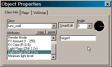
Now let's look at another way to control shadows. Along with Light Flags there is more Light Origin.
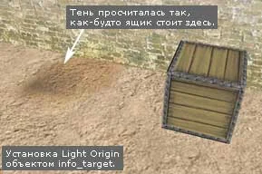
This parameter specifies the name of the object info_target, which is inherently a target object. Thus, when calculating lighting, the brush entity object will be temporarily moved to the object's place info_target, whose name is specified in the parameter Light Origin. Look at the picture below.
The shadow of the box is calculated at the location where the info_target object is installed
Where the shadow is is where the object is actually placed info_target with name target1. The same name is specified in the mailbox properties func_wall in the parameter Light Origin (see picture below).
t7shaddow5 It's hard to say in what cases it can be used Light Origin. Unlike Light Flags it is used very rarely.
Advice: do not block light on moving or destructible objects, as... the shadow is calculated and will not go anywhere when the object's position changes.
8.8

Fire

In this article we will talk about creating fire (simple and more complex designs). To implement these two types of lights, we need the following entity objects:

1. Simple fire

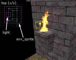
First, let's create a simple fire. To do this we need only two objects: light And env_sprite. We will use the remaining objects to create various special effects (see Part II of the article).
So, first, let's decide on the place where the fire will burn. It could be a torch or some kind of bowl. You can simply place the fire on the ground in the form of a bonfire.
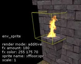
To create fire, animated sprites depicting fire are used (files *.spr), which are in the folder cstrike/sprites.. or, if they are not there, then in the pak0.pak archive in the valve folder. We will use a standard fire sprite named xffloor.spr. All you need to do is place a point entity object on the map in the right place env_sprite (see picture below).
Create an env_sprite object
Now you need to set some properties env_sprite.
Render Mode — Additive (this mode removes the black background around the sprite);
FX Amount — 180 (the degree of transparency of the sprite; more is more transparent);
FX Color — 255 175 70 (color of fire, in this case orange);
Sprite Name — sprites/xffloor.spr (the path to the file with the fire sprite is indicated here)
Scale — 1 (sprite scale. If you need larger or smaller fire, then change the sprite scale. Any values ​​are possible, for example: 0.2, 0.45, 0.8, 1, 2, 3.5, etc.)
Now go to the flags and check Start onso that the sprite animation automatically starts playing at the beginning of the round, otherwise the fire will "stand still")
The fire itself, because is a sprite and does not emit light. Therefore, in order for there to be light around the fire, it is necessary to insert a light source - an ordinary light (see picture below).
Create a light bulb next to the fire, the light object
Properties light:
Brightness — 255 210 135 80 (light orange light of medium brightness)
That's all - simple fire is ready.

2. More complex, but also more realistic fire

Complex fire can be called more advanced, more realistic. How does it differ from the simple fire just discussed?
Advanced fire has a burning sound, advanced fire has a glow (haze) around it, and when hit by advanced fire, the player receives damage. Well, let's implement all this.
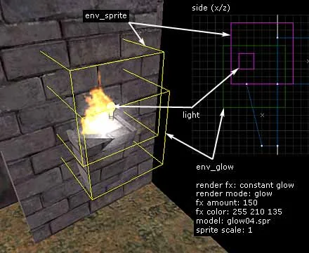
Let's turn simple fire into advanced. First, let's create a glow (haze) around the flame. The haze is created in a way already known to us using a point entity object env_glow. Let's insert this object into the center of the fire. In the picture below the fire itself (object env_sprite) is located just above the "haze" - env_glow. These objects almost coincide with each other, but still almost...
Create a haze around the fire using the env_glow object. We place it in almost the same place as env_sprite
To create the haze we will use a sprite glow04.spr from folder cstrike/sprites.. Let's set the properties env_glow.
Render FX — Constant Glow (can also be set to Normal, see below)
Render Mode - Glow (env_glow should always have this mode)
FX Amount — 150 (the higher the value, the brighter and more noticeable the haze. Maximum: 255)
FX Color — 255 210 135 (haze color, in this case light orange)
Model — sprites/glow04.spr (the path to the sprite file is indicated here)
Sprite Scale — 1 (sprite scale. The larger the scale, the more haze)
Now more about the parameter Render FX. For sprites it is recommended to set 2 modes: Normal or Constant Glow.
The only difference between these modes lies in the different intensity (brightness, saturation) haze when the player approaches/moves away from the sprite.
In mode Normal As the player moves away from the sprite, its brightness decreases and the sprite becomes less visible. At Constant Glow The sprite always has a constant brightness, regardless of the player's viewing distance. Try both options, sometimes Normal looks better, sometimes Constant Glow.
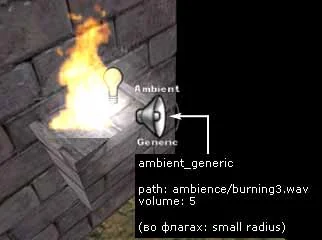
The haze is ready. Now let's insert the sound of fire. To do this, we use a point entity object ambient_generic. Insert it somewhere near the fire (see picture below).
Create a fire sound, ambient_generic object
Let's set the properties ambient_generic.
Path/filename.wav of WAV — ambience/burning3.wav (path to the sound file in WAV format). If in a folder cstrike/sound/ambience.. If you don't have such a sound, then use the PakExplorer program and remove this sound from the pak0.pak archive in the valve folder;
Volume — 5 (sound volume. The loudest is 10. We are using a not very large fire, so we set the volume low)
The remaining parameters are unimportant and can be left unset.
Now go to the flags and check Small Radius. This means that the sound will be heard a short distance from the fire. We also sorted out the sound.
Lastly, the player walking through the fire must take damage. If you leave everything as is, then you can walk through the fire painlessly. Some players don't like it when they get damaged, others, oddly enough, do :) It's a double-edged sword...
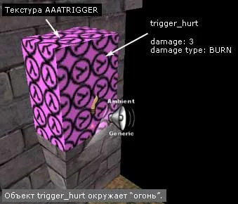
A brush entity object is used to cause damage trigger_hurt. The dimensions of this object determine the area, upon entering which the player will be damaged, so place trigger_hurt necessary around the fire, i.e. the fire must be located inside trigger_hurt.
Choose a special texture AAATrigger and create a regular brush around the fire (see picture below). Select it and click [Ctrl-T], select from the list trigger_hurt.
We create an area where the player will be damaged, a trigger_hurt object
Let's set the properties trigger_hurt, indicating the type of damage and its severity.
Damage — 3 (number of damage inflicted per second);
Damage Type — BURN (type of damage, in this case from fire. Affects only the icon displayed in the game on the screen, i.e. when damage from fire is a fire icon, etc.).
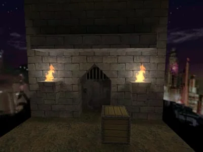
As a result of all our torment, we should get a rather beautiful and realistic fire (see figure below).
This is what both flames look like in the game
On our example map, we placed a box near the right torch so that you can jump into the fire and check how it works trigger_hurt :)
So, we have taught you how to create fire of the most complex design. Whether or not to use all these "bells and whistles" is up to you. For example, it is quite possible to do without haze and damage, limiting yourself only to the fire and sound itself.
fire.zip [81Kb] - in the archive there is an example map in BSP and RMF formats, as well as the necessary sprites and sounds.